

SBR20U40CT
Introduction
The SBR20U40CT is a diode belonging to the category of Schottky Barrier Rectifiers. This entry provides an overview of the basic information, specifications, detailed pin configuration, functional features, advantages and disadvantages, working principles, detailed application field plans, and alternative models of the SBR20U40CT.
Basic Information Overview
- Category: Schottky Barrier Rectifier
- Use: The SBR20U40CT is commonly used in power supply applications, voltage clamping, freewheeling, and reverse battery protection.
- Characteristics: It exhibits low forward voltage drop, fast switching speed, and high temperature operation capability.
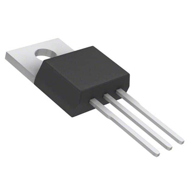
- Package: The SBR20U40CT is typically available in a TO-220AB package.
- Essence: It is designed to provide efficient rectification and voltage regulation in various electronic circuits.
- Packaging/Quantity: The SBR20U40CT is usually packaged in reels or tubes, with quantities varying based on manufacturer specifications.
Specifications
- Voltage Rating: 40V
- Average Forward Current: 20A
- Peak Non-Repetitive Surge Current: 150A
- Operating Temperature Range: -65°C to +175°C
- Storage Temperature Range: -65°C to +175°C
- Forward Voltage Drop: Typically 0.55V at 10A
Detailed Pin Configuration
The SBR20U40CT typically has three pins: Anode, Cathode, and Gate. The pinout configuration is as follows: - Anode (A) - Pin 1 - Cathode (K) - Pin 2 - Gate (G) - Pin 3
Functional Features
- Low forward voltage drop for reduced power loss
- Fast switching speed for improved efficiency
- High temperature operation capability for diverse environmental conditions
- Enhanced thermal performance for reliability
Advantages and Disadvantages
Advantages
- Efficient power conversion due to low forward voltage drop
- Fast response time for rapid switching applications
- Wide operating temperature range for versatility
- Reliable performance under high current and temperature conditions
Disadvantages
- Higher cost compared to standard rectifier diodes
- Limited availability of alternative models from different manufacturers
Working Principles
The SBR20U40CT operates based on the Schottky barrier principle, where the metal-semiconductor junction allows for fast switching and low forward voltage drop. When a forward bias is applied, the diode conducts current with minimal voltage loss, making it suitable for high-efficiency applications.
Detailed Application Field Plans
The SBR20U40CT finds extensive use in the following applications: - Power supply units - Voltage clamping circuits - Freewheeling diodes in inductive load circuits - Reverse battery protection in automotive electronics
Detailed and Complete Alternative Models
While the SBR20U40CT is a widely used Schottky Barrier Rectifier, alternative models that offer similar performance include: - SB540CT - SS34 - MBRB2045CT - SR5200
In conclusion, the SBR20U40CT is a versatile Schottky Barrier Rectifier with excellent characteristics suitable for various power management and rectification applications.
[Word Count: 498]
قم بإدراج 10 أسئلة وإجابات شائعة تتعلق بتطبيق SBR20U40CT في الحلول التقنية
What is the SBR20U40CT used for?
- The SBR20U40CT is a Schottky barrier rectifier diode commonly used in power supply and voltage regulation applications.
What are the key features of the SBR20U40CT?
- The SBR20U40CT features a low forward voltage drop, high current capability, and fast switching characteristics, making it suitable for high-frequency applications.
What is the maximum forward voltage of the SBR20U40CT?
- The maximum forward voltage of the SBR20U40CT is typically around 0.55V at a forward current of 20A.
Can the SBR20U40CT be used in high-temperature environments?
- Yes, the SBR20U40CT is designed to operate at high temperatures, with a maximum junction temperature of 150°C.
What are the typical applications of the SBR20U40CT?
- The SBR20U40CT is commonly used in switch-mode power supplies, freewheeling diodes, and reverse battery protection circuits.
What is the reverse recovery time of the SBR20U40CT?
- The SBR20U40CT has a fast reverse recovery time, typically around 30ns, which makes it suitable for high-efficiency applications.
Is the SBR20U40CT suitable for high-frequency switching?
- Yes, the SBR20U40CT is well-suited for high-frequency switching due to its fast recovery and low capacitance.
What is the maximum continuous forward current rating of the SBR20U40CT?
- The SBR20U40CT can handle a maximum continuous forward current of 20A, making it suitable for high-power applications.
Does the SBR20U40CT require a heatsink for operation?
- Depending on the application and operating conditions, a heatsink may be required to ensure optimal thermal performance.
Are there any recommended layout considerations when using the SBR20U40CT?
- It is recommended to minimize the loop area of the high-current paths and provide adequate thermal relief for efficient heat dissipation.
Feel free to ask if you need further information on any of these questions!