

IXGA20N60B
Introduction
The IXGA20N60B is a power semiconductor device that belongs to the category of Insulated Gate Bipolar Transistors (IGBTs). This entry provides an overview of the basic information, specifications, detailed pin configuration, functional features, advantages and disadvantages, working principles, detailed application field plans, and alternative models of the IXGA20N60B.
Basic Information Overview
- Category: Insulated Gate Bipolar Transistor (IGBT)
- Use: Power switching applications in various electronic devices and systems
- Characteristics: High voltage capability, low saturation voltage, fast switching speed
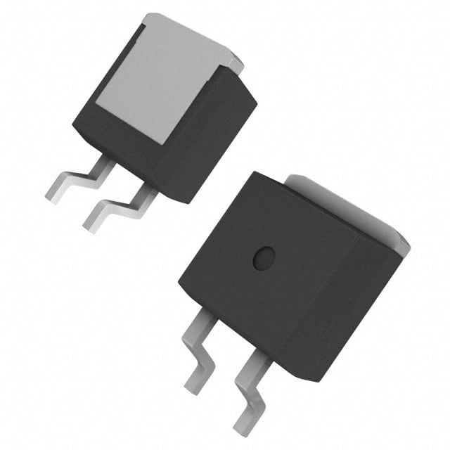
- Package: TO-220AB
- Essence: Power semiconductor for efficient power control
- Packaging/Quantity: Typically available in reels or tubes containing multiple units
Specifications
- Voltage Rating: 600V
- Current Rating: 20A
- Maximum Power Dissipation: 150W
- Operating Temperature Range: -55°C to 150°C
- Gate-Emitter Voltage: ±20V
- Collector-Emitter Saturation Voltage: 1.8V at 10A
Detailed Pin Configuration
The IXGA20N60B IGBT typically has three pins: 1. Collector (C) 2. Gate (G) 3. Emitter (E)
Functional Features
- High voltage capability suitable for power applications
- Low saturation voltage leading to reduced power losses
- Fast switching speed enabling efficient power control
Advantages and Disadvantages
Advantages
- High voltage capability
- Low saturation voltage
- Fast switching speed
- Suitable for power applications
Disadvantages
- Sensitivity to overvoltage conditions
- Limited operating temperature range
Working Principles
The IXGA20N60B operates based on the principles of controlling the flow of current between the collector and emitter terminals using the gate signal. When a suitable voltage is applied to the gate terminal, it allows the current to flow between the collector and emitter, enabling power control in electronic circuits.
Detailed Application Field Plans
The IXGA20N60B finds extensive use in various applications, including: - Motor drives - Uninterruptible power supplies (UPS) - Renewable energy systems - Induction heating systems - Welding equipment
Detailed and Complete Alternative Models
Some alternative models to the IXGA20N60B include: - IXGA30N60B: Higher current rating variant - IXGA15N60B: Lower current rating variant - IXGH20N60B: Higher voltage rating variant
In conclusion, the IXGA20N60B is a versatile IGBT with high voltage capability, low saturation voltage, and fast switching speed, making it suitable for a wide range of power switching applications in various electronic systems.
Word count: 386
قم بإدراج 10 أسئلة وإجابات شائعة تتعلق بتطبيق IXGA20N60B في الحلول التقنية
What is the maximum voltage rating of IXGA20N60B?
- The maximum voltage rating of IXGA20N60B is 600V.
What is the continuous current rating of IXGA20N60B?
- The continuous current rating of IXGA20N60B is 20A.
Can IXGA20N60B be used in high-frequency applications?
- Yes, IXGA20N60B can be used in high-frequency applications due to its fast switching characteristics.
What type of package does IXGA20N60B come in?
- IXGA20N60B comes in a TO-247 package.
Is IXGA20N60B suitable for motor control applications?
- Yes, IXGA20N60B is suitable for motor control applications due to its high current and voltage ratings.
Does IXGA20N60B have built-in protection features?
- Yes, IXGA20N60B has built-in overcurrent and overtemperature protection features.
What is the typical on-state voltage drop of IXGA20N60B?
- The typical on-state voltage drop of IXGA20N60B is around 1.8V at 20A.
Can IXGA20N60B be used in power factor correction circuits?
- Yes, IXGA20N60B can be used in power factor correction circuits due to its high voltage and current handling capabilities.
What is the maximum junction temperature of IXGA20N60B?
- The maximum junction temperature of IXGA20N60B is 150°C.
Is IXGA20N60B RoHS compliant?
- Yes, IXGA20N60B is RoHS compliant, making it suitable for environmentally friendly technical solutions.