

IXTT10P60
Introduction
The IXTT10P60 is a power semiconductor device belonging to the category of Insulated Gate Bipolar Transistors (IGBTs). This entry provides an overview of the basic information, specifications, pin configuration, functional features, advantages and disadvantages, working principles, application field plans, and alternative models of the IXTT10P60.
Basic Information Overview
- Category: Insulated Gate Bipolar Transistor (IGBT)
- Use: Power switching applications in various electronic systems
- Characteristics: High voltage capability, low saturation voltage, fast switching speed
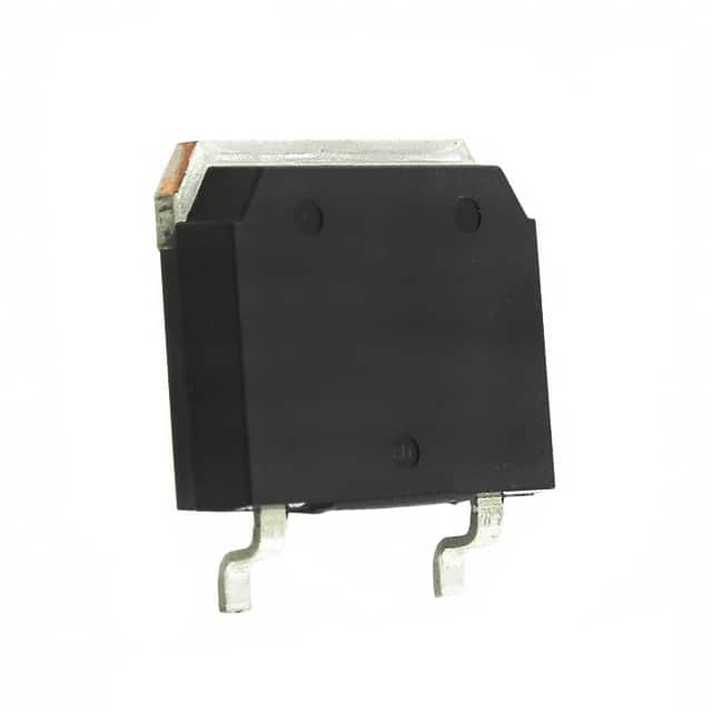
- Package: TO-220AB
- Essence: Power control and conversion
- Packaging/Quantity: Typically packaged individually
Specifications
- Voltage Rating: 600V
- Current Rating: 10A
- Maximum Power Dissipation: 150W
- Operating Temperature Range: -55°C to 150°C
- Gate-Emitter Voltage (VGE): ±20V
- Collector-Emitter Voltage (VCE): 600V
Detailed Pin Configuration
The IXTT10P60 typically has the following pin configuration: 1. Collector (C) 2. Gate (G) 3. Emitter (E)
Functional Features
- High voltage capability suitable for power applications
- Low saturation voltage leading to reduced power losses
- Fast switching speed enabling efficient power control
Advantages and Disadvantages
Advantages
- High voltage capability
- Low saturation voltage
- Fast switching speed
- Suitable for power applications
Disadvantages
- Sensitive to overvoltage conditions
- Requires careful handling during installation
Working Principles
The IXTT10P60 operates based on the principles of controlling the flow of current between its collector and emitter terminals using the gate signal. When a suitable voltage is applied to the gate terminal, it allows the current to flow between the collector and emitter, effectively controlling the power flow through the device.
Detailed Application Field Plans
The IXTT10P60 finds extensive use in various power electronics applications, including: - Motor drives - Uninterruptible power supplies (UPS) - Renewable energy systems - Industrial power control systems
Detailed and Complete Alternative Models
Some alternative models to the IXTT10P60 include: - IXTT08N100D - IXTT12N100D - IXTT15N120D - IXTT20N120D
In summary, the IXTT10P60 is a high-voltage IGBT with characteristics suitable for power switching applications. Its fast switching speed and low saturation voltage make it an ideal choice for various power control and conversion systems.
[Word count: 366]
قم بإدراج 10 أسئلة وإجابات شائعة تتعلق بتطبيق IXTT10P60 في الحلول التقنية
What is IXTT10P60?
- IXTT10P60 is a high power insulated gate bipolar transistor (IGBT) designed for various technical solutions requiring high voltage and current handling capabilities.
What are the key features of IXTT10P60?
- The key features of IXTT10P60 include a high voltage rating, low saturation voltage, fast switching speed, and rugged construction for reliable performance in demanding applications.
In what technical solutions can IXTT10P60 be used?
- IXTT10P60 can be used in applications such as motor drives, power supplies, renewable energy systems, welding equipment, and industrial automation where high power switching is required.
What is the maximum voltage and current rating of IXTT10P60?
- IXTT10P60 has a maximum voltage rating of [insert voltage] and a maximum current rating of [insert current], making it suitable for high power applications.
How does IXTT10P60 compare to other IGBTs in its class?
- IXTT10P60 offers superior performance in terms of voltage and current handling, low saturation voltage, and robustness, making it a preferred choice for demanding technical solutions.
What are the thermal characteristics of IXTT10P60?
- IXTT10P60 features excellent thermal conductivity and low thermal resistance, allowing for efficient heat dissipation and ensuring reliable operation under high temperature conditions.
Does IXTT10P60 require any special driver circuitry?
- IXTT10P60 may require a specific gate driver circuit to ensure optimal switching performance and protection against overvoltage or overcurrent conditions.
Can IXTT10P60 be used in parallel configurations for higher power applications?
- Yes, IXTT10P60 can be used in parallel configurations to increase the overall power handling capability, provided that proper current sharing and thermal management measures are implemented.
What protection features does IXTT10P60 offer?
- IXTT10P60 may include built-in protection features such as overcurrent protection, short-circuit protection, and temperature sensing to safeguard the device and the overall system.
Where can I find detailed application notes and technical specifications for IXTT10P60?
- Detailed application notes and technical specifications for IXTT10P60 can be found on the manufacturer's website or by contacting their technical support team for assistance.