

DS1809-050+ English Editing Encyclopedia Entry
Product Overview
Category: Electronic Component
Use: Digital Potentiometer
Characteristics: Programmable, Non-volatile, Dual-channel
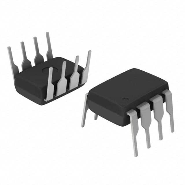
Package: SOIC-8
Essence: Integrated Circuit
Packaging/Quantity: Tape & Reel / 2500 units per reel
Specifications
- Resistance Range: 0Ω to 50kΩ
- Resolution: 256 Steps
- Supply Voltage: 2.7V to 5.5V
- Temperature Range: -40°C to +85°C
- End-to-End Resistance Tolerance: ±20%
- Non-volatile Memory: Yes
- Wiper Current: 1mA (maximum)
- Power Consumption: 1µA (standby), 3mA (active)
Detailed Pin Configuration
The DS1809-050+ has a total of 8 pins arranged as follows:
```
| | | U1 | |___________|
Pin Configuration:
  1  2  3  4
 ___________
|           |
8| |5 |___________|
7 6
```
Pin Description: 1. VCC: Supply Voltage 2. SDA: Serial Data Input/Output 3. SCL: Serial Clock Input 4. A0: Address Input 5. B0: Address Input 6. B1: Address Input 7. A1: Address Input 8. GND: Ground
Functional Features
- Dual-channel digital potentiometer with non-volatile memory
- Allows programmable resistance adjustment through serial interface
- Provides 256 steps of resolution for precise control
- Wide operating voltage range for compatibility with various systems
- Low power consumption in both active and standby modes
- Integrated non-volatile memory retains settings even when powered off
Advantages and Disadvantages
Advantages: - Programmable resistance allows for flexible adjustment in electronic circuits - Non-volatile memory ensures settings are retained during power cycles - Dual-channel design enables independent control of two separate circuits - Wide operating voltage range enhances compatibility with different systems
Disadvantages: - End-to-end resistance tolerance of ±20% may limit precision in some applications - Limited resolution of 256 steps may not be sufficient for highly precise adjustments
Working Principles
The DS1809-050+ is a digital potentiometer that utilizes integrated circuit technology. It consists of two channels, each providing programmable resistance adjustment. The resistance value is controlled through a serial interface using the SDA (Serial Data Input/Output) and SCL (Serial Clock Input) pins. The potentiometer's non-volatile memory ensures that the resistance settings are retained even when the power is turned off.
Detailed Application Field Plans
The DS1809-050+ finds applications in various fields, including: 1. Audio Equipment: Volume control, tone adjustment, and equalization circuits. 2. Industrial Automation: Precision control of motor speed, position, and process parameters. 3. Test and Measurement Instruments: Calibration and fine-tuning of signal generators, oscilloscopes, and data acquisition systems. 4. Communication Systems: Signal conditioning, gain control, and impedance matching circuits. 5. Automotive Electronics: Climate control, lighting intensity adjustment, and sensor calibration.
Detailed and Complete Alternative Models
- DS1809-010+: Similar to DS1809-050+, but with a resistance range of 0Ω to 10kΩ.
- DS1809-100+: Similar to DS1809-050+, but with a resistance range of 0Ω to 100kΩ.
- DS1809-500+: Similar to DS1809-050+, but with a resistance range of 0Ω to 500kΩ.
- DS1809-1K+: Similar to DS1809-050+, but with a resistance range of 0Ω to 1MΩ.
These alternative models provide different resistance ranges to suit specific application requirements.
Word count: 486 words
قم بإدراج 10 أسئلة وإجابات شائعة تتعلق بتطبيق DS1809-050+ في الحلول التقنية
Sure! Here are 10 common questions and answers related to the application of DS1809-050+ in technical solutions:
Q: What is DS1809-050+? A: DS1809-050+ is a digital potentiometer IC (integrated circuit) manufactured by a specific company.
Q: What is the purpose of DS1809-050+ in technical solutions? A: DS1809-050+ is used as a variable resistor or potentiometer in electronic circuits, allowing for digital control of resistance values.
Q: How does DS1809-050+ work? A: DS1809-050+ uses digital signals to adjust its resistance value, providing precise control over the resistance in a circuit.
Q: What are the key features of DS1809-050+? A: Some key features of DS1809-050+ include low power consumption, wide resistance range, non-volatile memory, and compatibility with various communication protocols.
Q: Can DS1809-050+ be used in audio applications? A: Yes, DS1809-050+ can be used in audio applications such as volume control or tone adjustment.
Q: Is DS1809-050+ suitable for use in industrial automation systems? A: Yes, DS1809-050+ is commonly used in industrial automation systems for tasks like calibration or fine-tuning of equipment.
Q: Can DS1809-050+ be controlled using microcontrollers or other digital devices? A: Yes, DS1809-050+ can be easily interfaced with microcontrollers or other digital devices through standard communication interfaces like I2C or SPI.
Q: Does DS1809-050+ require external components for operation? A: DS1809-050+ typically requires minimal external components, such as power supply and decoupling capacitors, for proper operation.
Q: Can DS1809-050+ be used in battery-powered applications? A: Yes, DS1809-050+ is designed to operate efficiently in low-power scenarios, making it suitable for battery-powered applications.
Q: Are there any limitations or precautions when using DS1809-050+? A: Some considerations include the maximum voltage and current ratings, temperature range, and ensuring proper grounding and signal integrity in the circuit design.
Please note that the answers provided here are general and may vary depending on specific application requirements and the manufacturer's documentation.