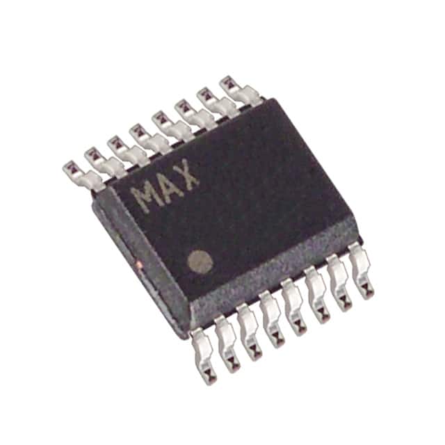
MAX4051CEE+ - English Editing Encyclopedia Entry
Product Overview
Category
MAX4051CEE+ belongs to the category of analog multiplexers/demultiplexers.
Use
It is primarily used for signal routing and switching applications in electronic circuits.
Characteristics
- Analog multiplexer with low on-resistance and low leakage current.
- Wide voltage range operation.
- High bandwidth and fast switching speed.
- Low power consumption.
- Compatible with various logic families.
Package
MAX4051CEE+ is available in a small-sized 16-pin SOIC (Small Outline Integrated Circuit) package.
Essence
The essence of MAX4051CEE+ lies in its ability to efficiently route and switch analog signals in electronic systems.
Packaging/Quantity
This product is typically packaged in reels or tubes, with a quantity of 2500 units per reel/tube.
Specifications
- Supply Voltage Range: +2.7V to +12V
- On-Resistance: 45Ω (typical)
- Leakage Current: 1nA (maximum)
- Bandwidth: 200MHz (typical)
- Switching Time: 100ns (maximum)
Detailed Pin Configuration
- IN1
- IN2
- IN3
- IN4
- IN5
- IN6
- IN7
- IN8
- VEE
- COM
- NO1
- NO2
- NO3
- NO4
- NO5
- NO6
Functional Features
- Single-ended or differential input/output configurations.
- Break-before-make switching action.
- Low crosstalk and distortion.
- ESD protection on all pins.
- Wide temperature range operation.
Advantages and Disadvantages
Advantages
- Low on-resistance ensures minimal signal attenuation.
- Fast switching speed allows for rapid signal routing.
- Wide voltage range compatibility enhances versatility.
- Low power consumption reduces energy requirements.
- ESD protection safeguards against electrostatic discharge.
Disadvantages
- Limited number of input/output channels (8 in this case).
- Higher cost compared to simpler analog switches.
- Requires external control signals for proper operation.
Working Principles
MAX4051CEE+ operates based on the principle of analog multiplexing. It uses a combination of MOSFET switches and control logic to selectively connect one of the input channels to the output channel(s). The control signals determine which input is connected to the output, allowing for signal routing and switching as desired.
Detailed Application Field Plans
MAX4051CEE+ finds applications in various fields, including but not limited to: 1. Audio/video signal routing in multimedia systems. 2. Data acquisition systems for sensor signal conditioning. 3. Test and measurement equipment for signal switching. 4. Communication systems for channel selection. 5. Industrial automation for signal routing in control circuits.
Detailed and Complete Alternative Models
Some alternative models that offer similar functionality to MAX4051CEE+ are: 1. CD4051B: CMOS analog multiplexer/demultiplexer with 8 channels. 2. ADG408: Precision CMOS analog multiplexer/demultiplexer with 8 channels. 3. DG408: Monolithic CMOS analog multiplexer/demultiplexer with 8 channels. 4. TS5A3357: Low-voltage bidirectional analog switch with 8 channels.
These alternative models can be considered based on specific application requirements and design constraints.
Word count: 536 words
قم بإدراج 10 أسئلة وإجابات شائعة تتعلق بتطبيق MAX4051CEE+ في الحلول التقنية
Sure! Here are 10 common questions and answers related to the application of MAX4051CEE+ in technical solutions:
Q1: What is the MAX4051CEE+? A1: The MAX4051CEE+ is a multiplexer/demultiplexer IC (integrated circuit) that allows multiple analog signals to be routed to a single output.
Q2: What is the purpose of using the MAX4051CEE+ in a technical solution? A2: The MAX4051CEE+ is commonly used to switch between different analog signals in applications such as audio/video routing, data acquisition systems, and instrumentation.
Q3: How many channels does the MAX4051CEE+ have? A3: The MAX4051CEE+ has 8 channels, which means it can handle up to 8 different analog signals.
Q4: What is the voltage range supported by the MAX4051CEE+? A4: The MAX4051CEE+ supports a wide voltage range from -5V to +5V, making it suitable for both bipolar and unipolar signals.
Q5: Can the MAX4051CEE+ handle high-frequency signals? A5: Yes, the MAX4051CEE+ has a bandwidth of 200MHz, allowing it to handle high-frequency signals with minimal distortion.
Q6: How is the MAX4051CEE+ controlled? A6: The MAX4051CEE+ is controlled through digital inputs, typically using microcontrollers or other digital logic circuits.
Q7: Can the MAX4051CEE+ be cascaded to increase the number of channels? A7: Yes, multiple MAX4051CEE+ ICs can be cascaded together to increase the number of channels and allow switching between more analog signals.
Q8: Does the MAX4051CEE+ require external power supply? A8: Yes, the MAX4051CEE+ requires an external power supply with a voltage range of +2.7V to +16V.
Q9: What is the package type of the MAX4051CEE+? A9: The MAX4051CEE+ is available in an 16-pin SOIC (Small Outline Integrated Circuit) package.
Q10: Are there any recommended applications or example circuits for the MAX4051CEE+? A10: Yes, the datasheet of the MAX4051CEE+ provides several application circuits and example designs, including audio/video switchers, data acquisition systems, and multiplexed sensor interfaces.
Please note that these answers are general and may vary depending on specific requirements and use cases. It's always recommended to refer to the datasheet and consult with technical experts for accurate information.


