

APT18F60B
Introduction
The APT18F60B is a power semiconductor device belonging to the category of insulated gate bipolar transistors (IGBTs). This entry provides an overview of the APT18F60B, including its basic information, specifications, pin configuration, functional features, advantages and disadvantages, working principles, application field plans, and alternative models.
Basic Information Overview
- Category: Insulated Gate Bipolar Transistor (IGBT)
- Use: Power switching applications in various electronic devices and systems
- Characteristics: High voltage and current handling capabilities, low on-state voltage drop, fast switching speed
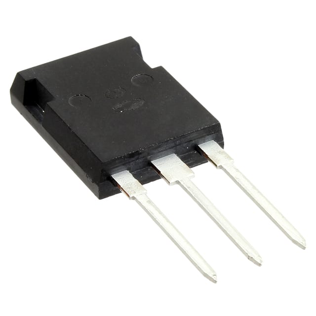
- Package: TO-247
- Essence: Power control and conversion
- Packaging/Quantity: Typically packaged individually, quantity varies based on manufacturer
Specifications
- Voltage Rating: 600V
- Current Rating: 18A
- Maximum Operating Temperature: 150°C
- Gate-Emitter Voltage: ±20V
- Collector-Emitter Saturation Voltage: 1.8V
- Turn-On Delay Time: 55ns
- Turn-Off Delay Time: 160ns
Detailed Pin Configuration
The APT18F60B typically has three main pins: 1. Collector (C): Connects to the high-voltage load or power supply 2. Emitter (E): Connected to the ground or low-side of the load 3. Gate (G): Input for controlling the switching operation
Functional Features
- Fast switching speed
- Low conduction losses
- High input impedance
- Robust thermal performance
Advantages and Disadvantages
Advantages
- Efficient power switching
- Reduced power dissipation
- Suitable for high-frequency applications
- Enhanced system reliability
Disadvantages
- Higher cost compared to traditional power transistors
- Sensitivity to overvoltage conditions
Working Principles
The APT18F60B operates based on the principles of IGBT technology, where it combines the advantages of MOSFETs and bipolar junction transistors (BJTs). It allows for efficient control of power flow in electronic circuits by modulating the conductivity between the collector and emitter terminals.
Detailed Application Field Plans
The APT18F60B finds extensive use in various applications, including: - Motor drives - Uninterruptible power supplies (UPS) - Renewable energy systems - Induction heating - Welding equipment
Detailed and Complete Alternative Models
Some alternative models to the APT18F60B include: - APT30D100B - IRG4BC20KD - FGA25N120ANTD
In conclusion, the APT18F60B serves as a crucial component in modern power electronics, offering high-performance characteristics and versatile applications across different industries.
(Word count: 368)
قم بإدراج 10 أسئلة وإجابات شائعة تتعلق بتطبيق APT18F60B في الحلول التقنية
What is the APT18F60B?
- The APT18F60B is a high-voltage, fast-switching N-channel IGBT (Insulated Gate Bipolar Transistor) designed for various power electronic applications.
What are the key features of the APT18F60B?
- The APT18F60B features a high voltage rating, low conduction and switching losses, and a rugged design suitable for demanding applications.
In what technical solutions can the APT18F60B be used?
- The APT18F60B can be used in applications such as motor drives, renewable energy systems, industrial automation, and power supplies.
What are the typical operating conditions for the APT18F60B?
- The APT18F60B operates at high voltages and currents, typically in the range of several hundred volts and tens to hundreds of amps.
How does the APT18F60B compare to other IGBTs in its class?
- The APT18F60B offers a balance of high voltage capability, low losses, and ruggedness, making it suitable for a wide range of applications.
What are the thermal considerations when using the APT18F60B?
- Proper heat sinking and thermal management are essential to ensure the APT18F60B operates within its temperature limits for reliable performance.
Are there any application notes or reference designs available for the APT18F60B?
- Yes, application notes and reference designs are available from the manufacturer to assist with the proper use of the APT18F60B in various technical solutions.
What protection features does the APT18F60B offer?
- The APT18F60B may include built-in features such as short-circuit protection, overcurrent protection, and temperature sensing to enhance system reliability.
Can the APT18F60B be paralleled for higher current applications?
- Yes, the APT18F60B can be paralleled to increase current handling capability, but careful attention must be paid to matching and balancing the devices.
Where can I find detailed specifications and application information for the APT18F60B?
- Detailed specifications and application information for the APT18F60B can be found in the datasheet provided by the manufacturer and on their official website.