

MRF544 Transistor
Product Category
The MRF544 transistor belongs to the category of high-frequency, high-power transistors used in RF (radio frequency) applications.
Basic Information Overview
- Use: The MRF544 transistor is commonly used in RF power amplifiers and other high-frequency applications.
- Characteristics: It is known for its high power handling capability and excellent performance at high frequencies.
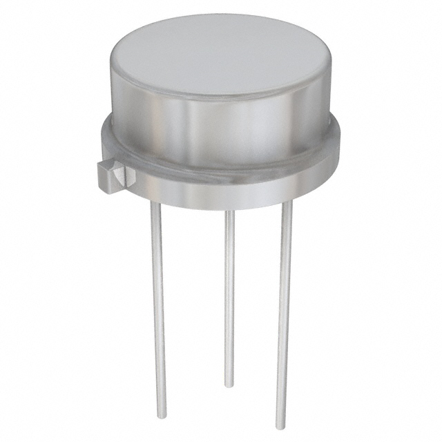
- Package: The MRF544 transistor is typically available in a metal-ceramic package for enhanced thermal performance.
- Essence: Its essence lies in providing high power amplification in RF circuits.
- Packaging/Quantity: The transistor is usually sold individually or in small quantities suitable for prototyping and small-scale production.
Specifications
- Frequency Range: Up to 500 MHz
- Power Output: Typically 30 watts
- Voltage Rating: 28 volts
- Current Rating: 5 amps
- Gain: 13 dB
Detailed Pin Configuration
The MRF544 transistor typically has three pins: 1. Emitter (E): Connected to the ground or common reference point. 2. Base (B): Input terminal for controlling the transistor's operation. 3. Collector (C): Output terminal for the amplified signal.
Functional Features
- High power gain at RF frequencies
- Good linearity and efficiency
- Suitable for class C amplifier designs
- Robust construction for reliable operation in demanding environments
Advantages and Disadvantages
Advantages
- High power handling capability
- Excellent performance at high frequencies
- Reliable and durable construction
- Suitable for high-efficiency amplifier designs
Disadvantages
- Limited frequency range compared to some newer transistor models
- Higher cost compared to lower power transistors
Working Principles
The MRF544 transistor operates based on the principles of amplifying RF signals. When biased and driven with an input signal, it amplifies the signal power at the output while maintaining good linearity and efficiency.
Detailed Application Field Plans
The MRF544 transistor finds application in various RF power amplifier circuits, including: - Amateur radio amplifiers - Broadcast transmitters - Radar systems - Industrial RF heating equipment
Detailed and Complete Alternative Models
Some alternative models to the MRF544 transistor include: - MRF150 - BLF278 - MRFE6VP61K25H
In conclusion, the MRF544 transistor is a reliable and high-performance component suitable for RF power amplification in various applications.
[Word Count: 324]
قم بإدراج 10 أسئلة وإجابات شائعة تتعلق بتطبيق MRF544 في الحلول التقنية
What is the MRF544 transistor used for?
- The MRF544 is a high-frequency, high-power NPN bipolar junction transistor (BJT) commonly used in RF amplifier applications.
What are the key specifications of the MRF544?
- The MRF544 typically operates at frequencies up to 175 MHz and can handle power levels of several watts.
How do I bias the MRF544 transistor?
- The MRF544 transistor can be biased using appropriate DC voltage and current levels to ensure proper operation in the desired application.
What are some common applications of the MRF544?
- The MRF544 is often used in RF power amplifiers, transmitters, and other high-frequency applications where moderate power levels are required.
What are the typical operating conditions for the MRF544?
- The MRF544 is designed to operate under specified voltage, current, and frequency ranges, which should be carefully considered in any technical solution.
How do I design an RF amplifier circuit using the MRF544?
- Designing an RF amplifier circuit with the MRF544 involves considerations such as impedance matching, biasing, and thermal management to ensure optimal performance.
What are the potential challenges when using the MRF544 in a technical solution?
- Challenges may include thermal management, stability in high-frequency circuits, and ensuring proper matching networks for efficient power transfer.
Can the MRF544 be used in linear amplifier designs?
- While the MRF544 is primarily used in non-linear amplifier applications, it can be utilized in linear amplifier designs with careful consideration of linearity and biasing.
Are there any recommended alternative transistors to the MRF544?
- Depending on specific requirements, alternative transistors such as the MRF581 or MRF580A may be suitable replacements for the MRF544 in certain applications.
Where can I find detailed application notes for using the MRF544 in technical solutions?
- Detailed application notes for the MRF544 can often be found in semiconductor manufacturer datasheets, RF design handbooks, and application-specific technical literature.