

Encyclopedia Entry: 74VHCT574ASJX
Product Overview
Category
The 74VHCT574ASJX belongs to the category of integrated circuits (ICs) and specifically falls under the family of flip-flops.
Use
This IC is commonly used in digital electronic systems for storing and transferring data. It is primarily employed in applications that require sequential logic operations, such as data registers, counters, and shift registers.
Characteristics
- High-speed operation: The 74VHCT574ASJX offers fast data transfer rates, making it suitable for time-critical applications.
- Low power consumption: This IC is designed to minimize power consumption, making it energy-efficient.
- Wide operating voltage range: It can operate within a wide voltage range, typically between 2V and 5.5V.
- Schmitt trigger inputs: The IC incorporates Schmitt trigger inputs, which provide hysteresis and improve noise immunity.
- Output drive capability: It has a high output drive capability, allowing it to drive capacitive loads efficiently.
Package and Quantity
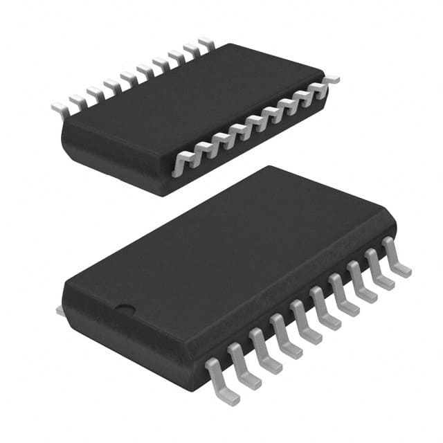
The 74VHCT574ASJX is available in a small-outline integrated circuit (SOIC) package. It consists of 20 pins arranged in a compact form factor. Typically, this IC is sold in reels or tubes containing multiple units, with quantities varying based on the supplier.
Specifications
- Supply Voltage Range: 2V to 5.5V
- Input Voltage Range: 0V to VCC
- Operating Temperature Range: -40°C to +85°C
- Maximum Clock Frequency: 100 MHz
- Output Current: ±6 mA
- Propagation Delay: 7 ns (max)
Pin Configuration
The 74VHCT574ASJX features 20 pins, each serving a specific function. Here is a detailed pin configuration:
- GND (Ground)
- D0 (Data Input 0)
- D1 (Data Input 1)
- D2 (Data Input 2)
- D3 (Data Input 3)
- D4 (Data Input 4)
- D5 (Data Input 5)
- D6 (Data Input 6)
- D7 (Data Input 7)
- OE (Output Enable)
- CP (Clock Pulse)
- MR (Master Reset)
- Q0 (Output 0)
- Q1 (Output 1)
- Q2 (Output 2)
- Q3 (Output 3)
- Q4 (Output 4)
- Q5 (Output 5)
- Q6 (Output 6)
- VCC (Supply Voltage)
Functional Features
The 74VHCT574ASJX offers the following functional features: - Data storage: It can store data on its eight input pins and retain it until a clock pulse triggers the transfer to the output pins. - Output enable control: The OE pin allows the user to enable or disable the outputs, providing flexibility in controlling data flow. - Master reset capability: The MR pin resets all flip-flops to their initial state when activated, ensuring a known starting point.
Advantages and Disadvantages
Advantages: - High-speed operation enables efficient data transfer. - Low power consumption makes it suitable for battery-powered devices. - Wide operating voltage range provides compatibility with various systems. - Schmitt trigger inputs enhance noise immunity. - Compact package size facilitates integration into space-constrained designs.
Disadvantages: - Limited number of flip-flops (eight in this case) may restrict certain applications requiring more storage capacity. - Propagation delay of 7 ns (maximum) may introduce timing constraints in high-speed applications.
Working Principles
The 74VHCT574ASJX operates based on the principles of positive-edge-triggered D-type flip-flops. It stores data on its input pins and transfers it to the output pins upon receiving a clock pulse. The output enable pin allows control over when the stored data is visible at the outputs. The master reset pin resets all flip-flops to their initial state, ensuring predictable behavior.
Application Field Plans
The 74VHCT574ASJX finds extensive use in various digital electronic systems, including but not limited to: - Microcontrollers and microprocessors - Communication devices (routers, switches) - Data storage systems - Industrial automation equipment - Automotive electronics
Alternative Models
For those seeking alternative options, several ICs can serve similar functions to the 74VHCT574ASJX. Some notable alternatives include: - SN74HC574N by Texas Instruments - CD74HCT574E by Texas Instruments - MC74VHC574DT by ON Semiconductor
These alternatives offer comparable features and performance characteristics, providing flexibility in choosing the
قم بإدراج 10 أسئلة وإجابات شائعة تتعلق بتطبيق 74VHCT574ASJX في الحلول التقنية
Sure! Here are 10 common questions and answers related to the application of 74VHCT574ASJX in technical solutions:
Q: What is the function of the 74VHCT574ASJX? A: The 74VHCT574ASJX is an octal D-type flip-flop with 3-state outputs. It can store and transfer data in digital circuits.
Q: What is the voltage range supported by the 74VHCT574ASJX? A: The 74VHCT574ASJX supports a voltage range of 4.5V to 5.5V.
Q: How many flip-flops are there in the 74VHCT574ASJX? A: The 74VHCT574ASJX contains 8 flip-flops, making it an octal (8-bit) device.
Q: Can the 74VHCT574ASJX be used for level shifting? A: Yes, the 74VHCT574ASJX can be used for level shifting as it supports both TTL and CMOS logic levels.
Q: What is the maximum clock frequency supported by the 74VHCT574ASJX? A: The maximum clock frequency supported by the 74VHCT574ASJX is typically around 100 MHz.
Q: Does the 74VHCT574ASJX have internal pull-up or pull-down resistors? A: No, the 74VHCT574ASJX does not have internal pull-up or pull-down resistors. External resistors may be required.
Q: Can the 74VHCT574ASJX be used for bidirectional data transfer? A: No, the 74VHCT574ASJX is unidirectional and can only transfer data in one direction.
Q: What is the power supply current consumption of the 74VHCT574ASJX? A: The power supply current consumption of the 74VHCT574ASJX is typically around 10-20 mA.
Q: Can the 74VHCT574ASJX be used in high-speed applications? A: Yes, the 74VHCT574ASJX is designed for high-speed operation and can be used in various high-frequency applications.
Q: Are there any specific precautions to consider when using the 74VHCT574ASJX? A: It is important to ensure proper decoupling capacitors are used near the power supply pins to minimize noise and voltage fluctuations. Additionally, care should be taken to avoid exceeding the maximum ratings specified in the datasheet.
Please note that these answers are general and may vary depending on the specific application and requirements. Always refer to the datasheet and consult with an expert for accurate information.