

HGTG20N60A4
Introduction
The HGTG20N60A4 is a power semiconductor device belonging to the category of Insulated Gate Bipolar Transistors (IGBTs). This entry provides an overview of the basic information, specifications, pin configuration, functional features, advantages and disadvantages, working principles, application field plans, and alternative models of the HGTG20N60A4.
Basic Information Overview
- Category: Insulated Gate Bipolar Transistor (IGBT)
- Use: Power switching applications in various electronic devices and systems.
- Characteristics: High voltage capability, low saturation voltage, fast switching speed.
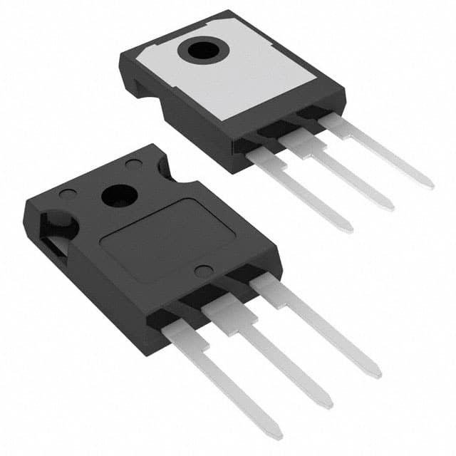
- Package: TO-247
- Essence: Power control and conversion in electronic circuits.
- Packaging/Quantity: Typically packaged individually.
Specifications
- Voltage Rating: 600V
- Current Rating: 40A
- Maximum Power Dissipation: 300W
- Operating Temperature Range: -55°C to 150°C
- Gate-Emitter Voltage: ±20V
Detailed Pin Configuration
The HGTG20N60A4 typically has three main pins: 1. Collector (C): Connects to the high-power load or circuit. 2. Emitter (E): Connected to the ground or return path. 3. Gate (G): Input terminal for controlling the switching action of the IGBT.
Functional Features
- High voltage capability allows for use in high-power applications.
- Low saturation voltage reduces power loss during operation.
- Fast switching speed enables efficient power control.
Advantages and Disadvantages
Advantages
- High voltage capability suitable for power electronics applications.
- Low saturation voltage minimizes power dissipation.
- Fast switching speed enhances efficiency in power control.
Disadvantages
- Susceptible to thermal runaway if not properly heat-sinked.
- Requires careful consideration of driving and protection circuitry.
Working Principles
The HGTG20N60A4 operates based on the principles of controlling the flow of current between the collector and emitter terminals through the application of a gate signal. When a suitable voltage is applied to the gate terminal, the IGBT allows current to flow, and when the gate signal is removed, the current flow ceases.
Detailed Application Field Plans
The HGTG20N60A4 finds extensive use in various applications including: - Motor drives - Uninterruptible power supplies (UPS) - Renewable energy systems - Induction heating equipment - Welding machines
Detailed and Complete Alternative Models
Some alternative models to the HGTG20N60A4 include: - IRG4PH40UD - FGA25N120ANTD - IXGH32N60B
In conclusion, the HGTG20N60A4 is a versatile IGBT with high voltage capability, low saturation voltage, and fast switching speed, making it suitable for a wide range of power switching applications across different industries.
[Word Count: 410]
قم بإدراج 10 أسئلة وإجابات شائعة تتعلق بتطبيق HGTG20N60A4 في الحلول التقنية
What is HGTG20N60A4?
- HGTG20N60A4 is a 600V, 40A IGBT (Insulated Gate Bipolar Transistor) designed for high power switching applications.
What are the typical applications of HGTG20N60A4?
- HGTG20N60A4 is commonly used in motor control, induction heating, and power supply applications.
What is the maximum voltage rating of HGTG20N60A4?
- The maximum voltage rating of HGTG20N60A4 is 600V, making it suitable for high voltage applications.
What is the maximum current rating of HGTG20N60A4?
- HGTG20N60A4 has a maximum current rating of 40A, allowing it to handle high current loads.
What are the key features of HGTG20N60A4?
- Some key features of HGTG20N60A4 include low saturation voltage, fast switching speed, and high ruggedness.
What is the thermal resistance of HGTG20N60A4?
- The thermal resistance of HGTG20N60A4 is typically around 1.25°C/W, which is important for managing heat dissipation.
Can HGTG20N60A4 be used in parallel configurations?
- Yes, HGTG20N60A4 can be used in parallel configurations to increase current handling capability in high power applications.
What are the recommended gate drive requirements for HGTG20N60A4?
- It is recommended to provide a gate drive voltage of 15V to 20V with sufficient current capability for optimal performance.
Does HGTG20N60A4 require external protection components?
- Yes, external protection components such as diodes, resistors, and snubbers may be required to ensure reliable operation and protect against voltage spikes.
Where can I find detailed technical specifications and application notes for HGTG20N60A4?
- Detailed technical specifications and application notes for HGTG20N60A4 can be found in the product datasheet provided by the manufacturer.