

MMBTA70LT1
Introduction
The MMBTA70LT1 is a versatile transistor belonging to the category of small signal transistors. This entry provides an overview of its basic information, specifications, detailed pin configuration, functional features, advantages and disadvantages, working principles, detailed application field plans, and alternative models.
Basic Information Overview
- Category: Small Signal Transistor
- Use: Amplification and Switching Applications
- Characteristics: High Voltage, Low Power Dissipation
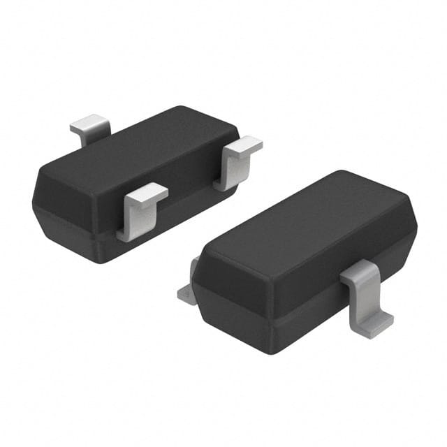
- Package: SOT-23
- Essence: NPN Bipolar Junction Transistor
- Packaging/Quantity: Tape & Reel, 3000 units per reel
Specifications
- Voltage - Collector Emitter Breakdown (Max): 40V
- Current - Collector (Ic) (Max): 100mA
- Power - Max: 225mW
- DC Current Gain (hFE) (Min) @ Ic, Vce: 40 @ 5mA, 10V
- Transition Frequency: 300MHz
Detailed Pin Configuration
The MMBTA70LT1 transistor has three pins: 1. Collector (C): Connects to the positive supply voltage in most applications. 2. Base (B): Controls the transistor's conductivity when a small current is applied. 3. Emitter (E): Allows the flow of current from the base to the collector.
Functional Features
- High Voltage Capability
- Low Leakage Current
- Fast Switching Speed
- Small Package Size
Advantages and Disadvantages
Advantages
- Suitable for high-speed switching applications
- Compact SOT-23 package
- Low power dissipation
Disadvantages
- Limited maximum current and voltage ratings
- Sensitive to temperature variations
Working Principles
The MMBTA70LT1 operates based on the principles of bipolar junction transistors. When a small current is applied to the base, it controls the larger current flowing between the collector and emitter, allowing for amplification or switching functions.
Detailed Application Field Plans
The MMBTA70LT1 is commonly used in various electronic circuits, including: - Audio Amplifiers - Signal Processing Circuits - Switching Circuits - Oscillator Circuits
Detailed and Complete Alternative Models
Some alternative models to the MMBTA70LT1 include: - 2N3904 - BC547 - 2N2222 - PN2222A
In conclusion, the MMBTA70LT1 is a small signal transistor with high voltage capability and low power dissipation, making it suitable for amplification and switching applications in various electronic circuits.
[Word Count: 366]
قم بإدراج 10 أسئلة وإجابات شائعة تتعلق بتطبيق MMBTA70LT1 في الحلول التقنية
What is MMBTA70LT1?
- MMBTA70LT1 is a general-purpose NPN transistor commonly used in electronic circuits for amplification and switching applications.
What are the typical applications of MMBTA70LT1?
- MMBTA70LT1 is often used in audio amplifiers, signal processing circuits, and voltage regulation applications.
What are the key electrical characteristics of MMBTA70LT1?
- The MMBTA70LT1 transistor typically has a maximum collector current of 600mA, a maximum collector-emitter voltage of 40V, and a DC current gain (hFE) of 100-250.
How do I identify the pin configuration of MMBTA70LT1?
- The pinout of MMBTA70LT1 is typically Emitter-Base-Collector (EBC), with the flat side facing towards you and the pins down, the left pin is the emitter, the middle pin is the base, and the right pin is the collector.
What are some common circuit designs using MMBTA70LT1?
- Common circuit designs include small signal amplifiers, switch-mode power supplies, and voltage regulators.
What are the thermal considerations when using MMBTA70LT1 in a design?
- It's important to consider proper heat sinking and thermal management to ensure the MMBTA70LT1 operates within its specified temperature range to avoid thermal runaway.
Are there any specific layout considerations when using MMBTA70LT1 in a PCB design?
- It's recommended to keep the traces short and minimize parasitic capacitance to reduce the risk of oscillation and instability in the circuit.
What are the alternatives to MMBTA70LT1 if it's not available?
- Alternatives to MMBTA70LT1 include similar NPN transistors such as 2N3904, BC547, or PN2222A, but it's important to check the datasheets and specifications to ensure compatibility.
How do I calculate the biasing and operating point for MMBTA70LT1 in a specific circuit?
- The biasing and operating point can be calculated using the transistor's datasheet specifications along with the desired circuit parameters and load requirements.
What are the best practices for soldering MMBTA70LT1 onto a PCB?
- It's important to use proper soldering techniques, such as using a temperature-controlled soldering iron and ensuring good solder joints without overheating the transistor, to prevent damage during assembly.