

NL7SZ18DFT2
Product Overview
Category: Integrated Circuit (IC)
Use: The NL7SZ18DFT2 is a high-speed CMOS single gate buffer designed for voltage level shifting and signal amplification in various electronic circuits.
Characteristics: - High-speed operation - Low power consumption - Wide operating voltage range - Small package size - RoHS compliant
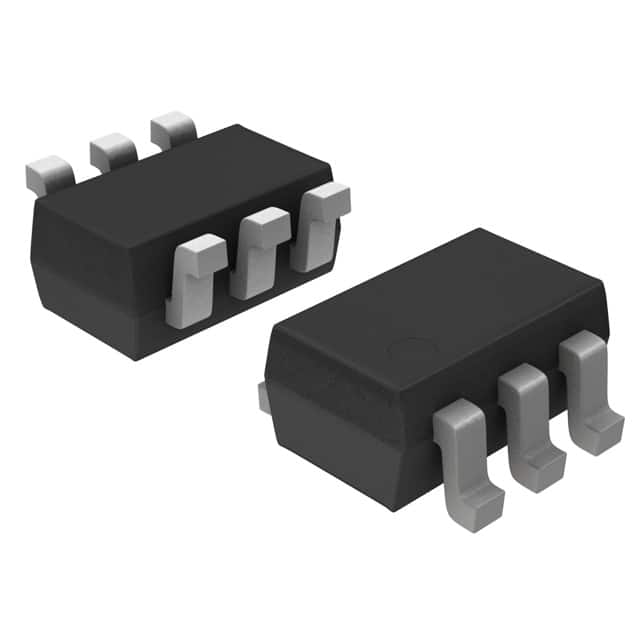
Package: The NL7SZ18DFT2 is available in a small SOT-353 package, which consists of three leads for easy soldering onto circuit boards.
Essence: This IC serves as a buffer to ensure proper voltage levels between different parts of an electronic circuit, preventing signal degradation and ensuring reliable data transmission.
Packaging/Quantity: The NL7SZ18DFT2 is typically sold in reels containing 3000 units per reel.
Specifications
- Supply Voltage Range: 1.65V to 5.5V
- Input Voltage Range: GND to VCC
- Output Voltage Range: GND to VCC
- Maximum Operating Frequency: 20 MHz
- Propagation Delay: 3.5 ns (typical)
- Input Capacitance: 2 pF (typical)
- Output Current: ±24 mA
Detailed Pin Configuration
The NL7SZ18DFT2 has the following pin configuration:
____
   A -|    |- VCC
   B -|    |- Y
GND/VSS -|____|- GND/VSS
Functional Features
- Voltage Level Shifting: The NL7SZ18DFT2 can shift input voltage levels to match the desired output voltage levels, allowing seamless integration of components with different voltage requirements.
- Signal Amplification: It provides signal amplification, ensuring strong and reliable signals throughout the circuit.
- High-Speed Operation: With a maximum operating frequency of 20 MHz, this IC is suitable for high-speed applications.
- Low Power Consumption: The NL7SZ18DFT2 consumes minimal power, making it ideal for battery-powered devices.
Advantages and Disadvantages
Advantages: - Wide operating voltage range allows compatibility with various systems. - Small package size enables space-saving designs. - RoHS compliance ensures environmental friendliness. - High-speed operation facilitates efficient data transmission. - Low power consumption prolongs battery life.
Disadvantages: - Limited output current may not be suitable for driving heavy loads. - Propagation delay may affect timing-sensitive applications.
Working Principles
The NL7SZ18DFT2 operates based on CMOS technology. It utilizes complementary pairs of MOSFET transistors to achieve voltage level shifting and signal amplification. When an input signal is applied, the internal circuitry amplifies and shifts the voltage levels accordingly, providing a clean and reliable output signal.
Detailed Application Field Plans
The NL7SZ18DFT2 finds applications in various electronic circuits, including but not limited to: 1. Logic level translation in microcontrollers and digital systems. 2. Signal buffering in communication systems. 3. Voltage level adaptation in sensor interfaces. 4. Clock signal distribution in high-speed data transmission. 5. Signal conditioning in audio amplifiers.
Detailed and Complete Alternative Models
- SN74LVC1G07DBVR - Single Buffer/Driver with Open-Drain Output
- MC74VHC1GT50DTT1G - Single Buffer/Driver with Schmitt Trigger Input
- TC7SZ08FU(T5L,F) - Single AND Gate
These alternative models offer similar functionality and can be used as substitutes for the NL7SZ18DFT2 in different applications.
Word count: 533
قم بإدراج 10 أسئلة وإجابات شائعة تتعلق بتطبيق NL7SZ18DFT2 في الحلول التقنية
Sure! Here are 10 common questions and answers related to the application of NL7SZ18DFT2 in technical solutions:
Q: What is NL7SZ18DFT2? A: NL7SZ18DFT2 is a specific type of integrated circuit (IC) or chip that belongs to the NL7 series. It is commonly used in various technical solutions.
Q: What is the function of NL7SZ18DFT2? A: NL7SZ18DFT2 is a single gate buffer with open-drain output. It is primarily used for voltage level shifting, signal buffering, and isolation purposes.
Q: What is the operating voltage range of NL7SZ18DFT2? A: The operating voltage range of NL7SZ18DFT2 typically ranges from 1.65V to 5.5V.
Q: Can NL7SZ18DFT2 be used in both digital and analog applications? A: No, NL7SZ18DFT2 is primarily designed for digital applications and is not recommended for use in analog circuits.
Q: What is the maximum output current of NL7SZ18DFT2? A: The maximum output current of NL7SZ18DFT2 is typically around 32mA.
Q: Is NL7SZ18DFT2 suitable for high-speed applications? A: Yes, NL7SZ18DFT2 is capable of operating at high speeds and is often used in applications where fast switching times are required.
Q: Can NL7SZ18DFT2 be used in battery-powered devices? A: Yes, NL7SZ18DFT2 has a low power consumption and can be used in battery-powered devices.
Q: What is the package type of NL7SZ18DFT2? A: NL7SZ18DFT2 is typically available in a small footprint SOT-353 package.
Q: Can NL7SZ18DFT2 be used in harsh environments? A: NL7SZ18DFT2 is not specifically designed for harsh environments and may require additional protection if used in such conditions.
Q: Are there any recommended alternatives to NL7SZ18DFT2? A: Yes, some alternative ICs that can perform similar functions to NL7SZ18DFT2 include SN74LVC1G07, NC7SZ04, and 74LVC1G125.
Please note that the answers provided here are general and may vary depending on specific datasheet specifications and application requirements.