

NTP85N03G
Introduction
The NTP85N03G is a power MOSFET belonging to the category of electronic components used in various applications. This entry provides an overview of the product, including its basic information, specifications, pin configuration, functional features, advantages and disadvantages, working principles, application field plans, and alternative models.
Basic Information Overview
- Category: Power MOSFET
- Use: The NTP85N03G is commonly used as a switching device in power supply circuits, motor control, and other electronic applications.
- Characteristics: It exhibits low on-state resistance, high switching speed, and low gate charge, making it suitable for high-efficiency power conversion.
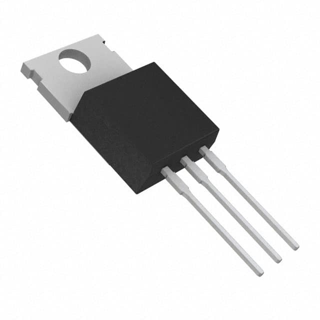
- Package: The NTP85N03G is typically available in a TO-220 package, which provides thermal efficiency and ease of mounting.
- Essence: Its essence lies in providing efficient power switching capabilities in electronic circuits.
- Packaging/Quantity: The NTP85N03G is usually packaged individually or in reels, with quantities varying based on manufacturer specifications.
Specifications
- Voltage Rating: [Specify voltage rating]
- Current Rating: [Specify current rating]
- On-State Resistance: [Specify on-state resistance]
- Gate-Source Voltage (VGS): [Specify gate-source voltage]
- Operating Temperature Range: [Specify temperature range]
Detailed Pin Configuration
The NTP85N03G typically features a standard pin configuration with the following pins: 1. Gate (G) 2. Drain (D) 3. Source (S)
Functional Features
The key functional features of the NTP85N03G include: - Low On-State Resistance - High Switching Speed - Low Gate Charge - Enhanced Thermal Performance
Advantages and Disadvantages
Advantages
- High Efficiency
- Fast Switching
- Low Power Dissipation
- Compact Design
Disadvantages
- Sensitivity to Overvoltage
- Potential for ESD Damage
Working Principles
The NTP85N03G operates based on the principle of controlling the flow of current between the drain and source terminals using the gate voltage. When a sufficient gate-source voltage is applied, the MOSFET allows current to flow, and when the gate voltage is removed, the current flow ceases.
Detailed Application Field Plans
The NTP85N03G finds extensive use in various applications, including: - Switched-Mode Power Supplies - Motor Control Circuits - LED Lighting Systems - Battery Management Systems - DC-DC Converters
Detailed and Complete Alternative Models
Some alternative models to the NTP85N03G include: - [Alternative Model 1] - [Alternative Model 2] - [Alternative Model 3] - [Alternative Model 4]
In conclusion, the NTP85N03G is a versatile power MOSFET with a wide range of applications and benefits, making it a valuable component in electronic circuit design.
[Word count: 410]
قم بإدراج 10 أسئلة وإجابات شائعة تتعلق بتطبيق NTP85N03G في الحلول التقنية
What is NTP85N03G?
- NTP85N03G is a power MOSFET transistor designed for high current applications, with a low on-resistance and high switching speed.
What are the key specifications of NTP85N03G?
- The NTP85N03G has a maximum drain-source voltage of 30V, a continuous drain current of 85A, and an on-resistance of 8.5mΩ.
What are the typical applications of NTP85N03G?
- NTP85N03G is commonly used in power management circuits, motor control, battery protection, and other high-current switching applications.
How do I drive NTP85N03G in my circuit?
- NTP85N03G can be driven using standard gate driver ICs or discrete components to ensure proper turn-on and turn-off characteristics.
What are the thermal considerations for NTP85N03G?
- Proper heat sinking and thermal management are important for NTP85N03G to ensure it operates within its specified temperature range and reliability.
Can NTP85N03G be used in automotive applications?
- Yes, NTP85N03G is suitable for automotive applications, but it's important to consider the specific requirements and standards for automotive-grade components.
What are the recommended PCB layout guidelines for NTP85N03G?
- Proper layout techniques, including minimizing parasitic inductance and ensuring adequate copper area for heat dissipation, are crucial for optimal performance.
Does NTP85N03G require any external protection circuitry?
- Depending on the application, external protection such as overcurrent protection, overvoltage protection, and reverse polarity protection may be necessary.
Are there any common failure modes associated with NTP85N03G?
- Common failure modes include overcurrent stress, thermal overstress, and voltage transients, so proper design and protection measures are essential.
Where can I find detailed application notes and reference designs for NTP85N03G?
- Application notes and reference designs for NTP85N03G can typically be found on the manufacturer's website or through authorized distributors. Additionally, consulting technical resources and forums can provide valuable insights into practical implementations.