

GBU1001TB Product Overview
Introduction
The GBU1001TB is a crucial component in the field of electronic devices, serving as a bridge rectifier. This entry will provide an in-depth overview of the product, covering its category, use, characteristics, packaging, specifications, pin configuration, functional features, advantages and disadvantages, working principles, application field plans, and alternative models.
Basic Information Overview
- Category: Electronic Components
- Use: Bridge Rectifier
- Characteristics: High efficiency, low power dissipation
- Package: Through Hole
- Essence: Converts alternating current (AC) to direct current (DC)
- Packaging/Quantity: Typically available in packs of 50 units
Specifications
- Maximum Average Forward Current: 10A
- Peak Repetitive Reverse Voltage: 1000V
- Operating Temperature Range: -55°C to +150°C
- Storage Temperature Range: -55°C to +150°C
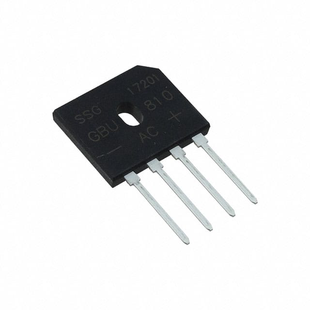
Detailed Pin Configuration
The GBU1001TB follows the standard pin configuration for bridge rectifiers, with four pins labeled as positive (+), negative (-), and two AC input pins.
Functional Features
- Efficiently converts AC to DC
- Low power dissipation
- Reliable performance under specified operating conditions
Advantages and Disadvantages
Advantages
- High efficiency
- Compact design
- Wide operating temperature range
Disadvantages
- Not suitable for high-frequency applications
- Requires heat sink for high current applications
Working Principles
The GBU1001TB operates on the principle of rectification, where it converts the incoming AC voltage into a pulsating DC output. This process involves the use of diodes arranged in a specific configuration to ensure the flow of current in one direction.
Detailed Application Field Plans
The GBU1001TB finds extensive use in various electronic devices and equipment, including: - Power supplies - Motor drives - Battery chargers - Welding equipment - Industrial automation systems
Detailed and Complete Alternative Models
For users seeking alternative bridge rectifiers, the following models can be considered: 1. GBU1002TB 2. GBU1003TB 3. GBU1004TB 4. GBU1005TB
In conclusion, the GBU1001TB serves as a vital component in electronic circuits, providing efficient rectification of AC power to DC. Its compact design, high efficiency, and wide operating temperature range make it a preferred choice for various applications in the electronics industry.
[Word Count: 398]
قم بإدراج 10 أسئلة وإجابات شائعة تتعلق بتطبيق GBU1001TB في الحلول التقنية
What is GBU1001TB?
- GBU1001TB is a bridge rectifier component commonly used in technical solutions to convert alternating current (AC) to direct current (DC).
What are the typical applications of GBU1001TB?
- GBU1001TB is commonly used in power supplies, industrial automation, motor control, and other electronic devices that require DC power.
What is the maximum voltage rating of GBU1001TB?
- The maximum voltage rating of GBU1001TB is typically around 1000 volts.
What is the maximum current rating of GBU1001TB?
- The maximum current rating of GBU1001TB is typically around 10 amps.
What are the key features of GBU1001TB?
- GBU1001TB typically features high surge current capability, low forward voltage drop, and high isolation voltage.
How do I select the right heat sink for GBU1001TB?
- The selection of a heat sink for GBU1001TB depends on the application's power dissipation requirements and thermal management considerations. It's important to consult the datasheet and consider the operating conditions.
What are the mounting options for GBU1001TB?
- GBU1001TB can be mounted using through-hole or surface mount techniques, depending on the specific package type.
What are the common failure modes of GBU1001TB?
- Common failure modes of GBU1001TB include overvoltage, overcurrent, and thermal overstress. Proper circuit protection and thermal management are essential to prevent these failures.
Can GBU1001TB be used in automotive applications?
- Yes, GBU1001TB can be used in certain automotive applications where its electrical and thermal characteristics meet the requirements.
Are there any recommended layout guidelines for using GBU1001TB in PCB designs?
- Yes, it's important to follow the recommended layout guidelines provided in the datasheet to ensure proper performance and reliability of GBU1001TB in PCB designs. This includes considerations for trace routing, thermal vias, and component placement.