

Encyclopedia Entry: 74AC16244DLR
Product Information Overview
- Category: Integrated Circuit (IC)
- Use: Buffer/Driver
- Characteristics: High-speed, low-power, 16-bit non-inverting buffer/line driver
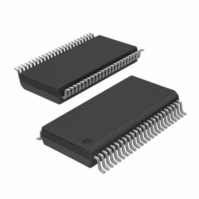
- Package: DIP-48 (Dual In-Line Package)
- Essence: The 74AC16244DLR is a versatile IC that provides high-speed buffering and line driving capabilities for digital signals.
- Packaging/Quantity: Available in reels or tubes, with varying quantities depending on the supplier.
Specifications
- Logic Family: AC
- Number of Bits: 16
- Input Voltage: 2V to 6V
- Output Voltage: 0V to VCC
- Propagation Delay: 5.5 ns (typical)
- Operating Temperature Range: -40°C to +85°C
Detailed Pin Configuration
The 74AC16244DLR has a total of 48 pins, arranged as follows:
┌───┬───┐
   A1 -|1  └─ 48|- VCC
   B1 -|2     47|- OE#
   A2 -|3     46|- Y1
   B2 -|4     45|- GND
   A3 -|5     44|- Y2
   B3 -|6     43|- Y3
   A4 -|7     42|- GND
   B4 -|8     41|- Y4
   A5 -|9     40|- Y5
   B5 -|10    39|- GND
   A6 -|11    38|- Y6
   B6 -|12    37|- Y7
   A7 -|13    36|- GND
   B7 -|14    35|- Y8
   A8 -|15    34|- Y9
   B8 -|16    33|- GND
   A9 -|17    32|- Y10
  A10 -|18    31|- Y11
  B10 -|19    30|- GND
  A11 -|20    29|- Y12
  B11 -|21    28|- Y13
  A12 -|22    27|- GND
  B12 -|23    26|- Y14
  A13 -|24    25|- Y15
       └───┴───┘
Functional Features
- Non-inverting buffer/line driver with 3-state outputs
- High-speed operation, suitable for use in applications requiring fast signal propagation
- Low power consumption, making it energy-efficient
- Wide operating voltage range allows compatibility with various digital systems
- 3-state outputs enable easy interfacing with other devices
Advantages and Disadvantages
Advantages: - High-speed operation ensures efficient signal transmission - Low power consumption reduces energy usage - Versatile 3-state outputs facilitate easy integration with other components - Wide operating voltage range enhances compatibility
Disadvantages: - Limited number of bits (16) may not be sufficient for certain applications requiring larger data sizes - DIP-48 package may occupy more space on a circuit board compared to smaller packages
Working Principles
The 74AC16244DLR operates as a non-inverting buffer and line driver. It takes digital input signals and amplifies them to provide high-speed, low-power output signals. The 3-state outputs allow the IC to be effectively disconnected from the bus, enabling multiple devices to share the same bus without interference.
Detailed Application Field Plans
The 74AC16244DLR is commonly used in various digital systems and applications, including:
- Microprocessor-based systems
- Data communication networks
- Industrial automation
- Instrumentation and measurement equipment
- Automotive electronics
- Consumer electronics
Detailed and Complete Alternative Models
- 74ACT16244DLR: Similar to 74AC16244DLR but operates at a different logic family (ACT)
- 74HC16244DLR: High-speed CMOS version with similar functionality
- 74HCT16244DLR: High-speed CMOS version with TTL compatibility
These alternative models offer similar features and can be used as substitutes depending on specific requirements and system compatibility.
Word Count: 470 words
قم بإدراج 10 أسئلة وإجابات شائعة تتعلق بتطبيق 74AC16244DLR في الحلول التقنية
Sure! Here are 10 common questions and answers related to the application of 74AC16244DLR in technical solutions:
Q: What is the 74AC16244DLR? A: The 74AC16244DLR is a 16-bit buffer/driver with 3-state outputs, commonly used in digital logic circuits.
Q: What is the purpose of the 74AC16244DLR? A: The purpose of this IC is to provide buffering and driving capabilities for signals in digital systems, ensuring proper signal transmission and isolation.
Q: What voltage levels does the 74AC16244DLR support? A: The 74AC16244DLR supports a wide range of voltage levels, typically between 2V and 6V.
Q: How many inputs and outputs does the 74AC16244DLR have? A: The 74AC16244DLR has 16 inputs and 16 outputs, making it suitable for handling 16-bit data.
Q: Can the 74AC16244DLR be used as a bidirectional buffer? A: No, the 74AC16244DLR is unidirectional and can only be used as a buffer or driver for signals in one direction.
Q: What is the maximum current that the 74AC16244DLR can drive? A: The 74AC16244DLR can typically drive up to 24mA of current per output pin.
Q: Does the 74AC16244DLR have internal pull-up or pull-down resistors? A: No, the 74AC16244DLR does not have internal pull-up or pull-down resistors. External resistors may be required for proper signal termination.
Q: Can the 74AC16244DLR handle high-speed signals? A: Yes, the 74AC16244DLR is designed to operate at high speeds, making it suitable for applications requiring fast signal propagation.
Q: Is the 74AC16244DLR compatible with other logic families? A: Yes, the 74AC16244DLR is compatible with a wide range of logic families, including TTL, CMOS, and LVTTL.
Q: What is the power supply voltage range for the 74AC16244DLR? A: The 74AC16244DLR typically operates with a power supply voltage between 2V and 6V, making it compatible with various digital systems.
Please note that these answers are general and may vary depending on specific datasheet specifications and application requirements.