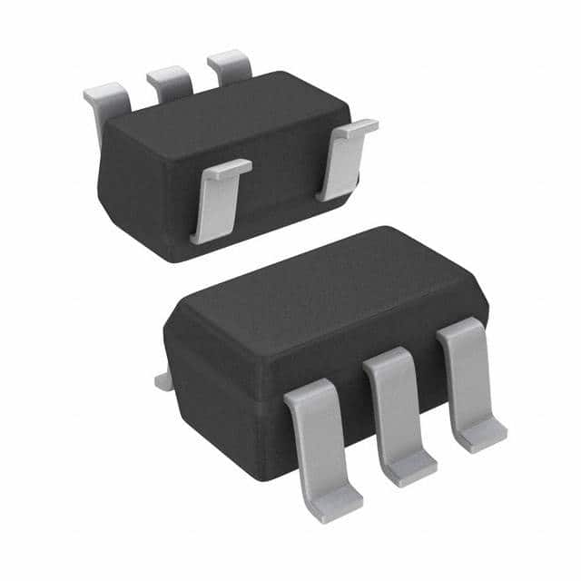
Encyclopedia Entry: 74AUC1G125DBVRG4
Product Overview
- Category: Integrated Circuit (IC)
- Use: Logic Buffer/Driver
- Characteristics: Single Gate, Non-Inverting, Tri-State Output
- Package: SOT-23-5
- Essence: High-Speed CMOS Technology
- Packaging/Quantity: Tape and Reel, 3000 pieces per reel
Specifications
The 74AUC1G125DBVRG4 is a logic buffer/driver IC that operates on a single power supply voltage. It is designed using high-speed CMOS technology, providing fast switching speeds and low power consumption. The device features a non-inverting tri-state output, allowing for bidirectional data flow. It is housed in a compact SOT-23-5 package, making it suitable for space-constrained applications.
Detailed Pin Configuration
The 74AUC1G125DBVRG4 has five pins arranged as follows: 1. Pin 1: Input (A) 2. Pin 2: Output (Y) 3. Pin 3: Enable (E) 4. Pin 4: Ground (GND) 5. Pin 5: Power Supply (VCC)
Functional Features
- Non-inverting Buffer: The IC amplifies the input signal without changing its logic level.
- Tri-State Output: The output can be disabled by setting the enable pin to a specific logic level, allowing multiple devices to share a common bus.
- High-Speed Operation: The IC offers fast switching speeds, enabling efficient data transmission in time-critical applications.
- Low Power Consumption: The device is designed to minimize power consumption, making it suitable for battery-powered devices.
Advantages and Disadvantages
Advantages: - Compact Size: The SOT-23-5 package allows for space-efficient integration into electronic circuits. - Bidirectional Data Flow: The tri-state output enables bidirectional communication between multiple devices. - High-Speed Operation: The IC's fast switching speeds facilitate efficient data transmission.
Disadvantages: - Limited Output Current: The device has a maximum output current rating, which may restrict its use in applications requiring higher current levels. - Single Gate Functionality: The IC is designed to perform a specific logic function and may not be suitable for complex circuit designs.
Working Principles
The 74AUC1G125DBVRG4 operates based on the principles of CMOS technology. It utilizes complementary pairs of MOSFET transistors to achieve high-speed switching and low power consumption. The input signal is amplified by the internal buffer, and the non-inverting nature of the device ensures that the output follows the input logic level. The tri-state output feature allows the device to be enabled or disabled, controlling the flow of data on the output pin.
Detailed Application Field Plans
The 74AUC1G125DBVRG4 can be used in various applications, including but not limited to: - Communication Systems - Computer Peripherals - Industrial Control Systems - Consumer Electronics - Automotive Electronics
Detailed and Complete Alternative Models
- 74AUC1G125DCKR
- SN74AUC1G125DCKR
- MC74AUC1G125DCKR
- TC7SZ125FU(TE12L,Q)
- NCV8402ASTT3G
These alternative models offer similar functionality and can be considered as replacements for the 74AUC1G125DBVRG4 in different applications.
Word count: 400 words
قم بإدراج 10 أسئلة وإجابات شائعة تتعلق بتطبيق 74AUC1G125DBVRG4 في الحلول التقنية
Sure! Here are 10 common questions and answers related to the application of 74AUC1G125DBVRG4 in technical solutions:
Q1: What is the 74AUC1G125DBVRG4? A1: The 74AUC1G125DBVRG4 is a single bus buffer gate with 3-state output. It is commonly used in digital logic circuits.
Q2: What is the operating voltage range of the 74AUC1G125DBVRG4? A2: The operating voltage range of the 74AUC1G125DBVRG4 is typically between 0.8V and 3.6V.
Q3: What is the maximum output current of the 74AUC1G125DBVRG4? A3: The maximum output current of the 74AUC1G125DBVRG4 is typically around 32mA.
Q4: Can the 74AUC1G125DBVRG4 be used as a level shifter? A4: Yes, the 74AUC1G125DBVRG4 can be used as a level shifter to convert signals between different voltage levels.
Q5: Does the 74AUC1G125DBVRG4 have internal pull-up or pull-down resistors? A5: No, the 74AUC1G125DBVRG4 does not have internal pull-up or pull-down resistors. External resistors may be required for pull-up or pull-down functionality.
Q6: What is the propagation delay of the 74AUC1G125DBVRG4? A6: The propagation delay of the 74AUC1G125DBVRG4 is typically around 2.5ns.
Q7: Can the 74AUC1G125DBVRG4 drive capacitive loads? A7: Yes, the 74AUC1G125DBVRG4 can drive small capacitive loads. However, for larger capacitive loads, additional buffering may be required.
Q8: Is the 74AUC1G125DBVRG4 suitable for high-speed applications? A8: The 74AUC1G125DBVRG4 is designed for low-power and low-voltage applications. It may not be suitable for high-speed applications with strict timing requirements.
Q9: Can the 74AUC1G125DBVRG4 be used in automotive applications? A9: Yes, the 74AUC1G125DBVRG4 is qualified for automotive applications and meets the necessary standards.
Q10: What is the package type of the 74AUC1G125DBVRG4? A10: The 74AUC1G125DBVRG4 is available in a SOT-23-5 package, which is a small surface-mount package commonly used in electronic devices.
Please note that the answers provided here are general and may vary depending on specific datasheet specifications or application requirements.


