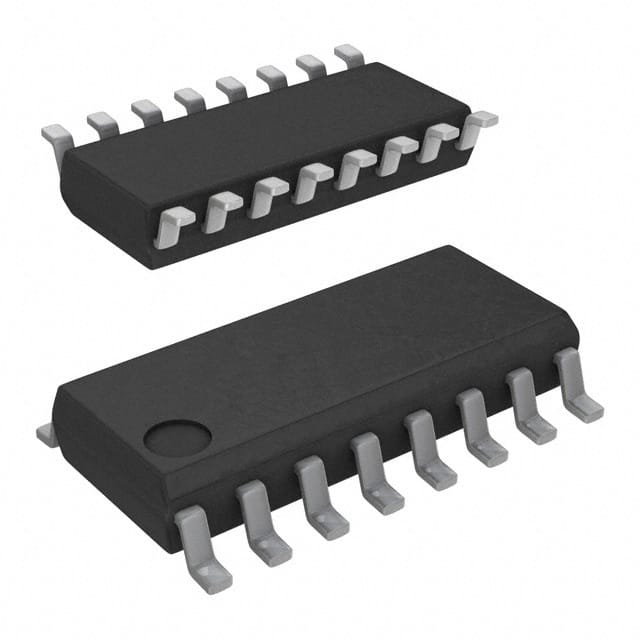
CD74HCT253M96
Product Overview
- Category: Integrated Circuit (IC)
- Use: Multiplexer/Demultiplexer
- Characteristics: High-Speed CMOS Logic, Dual 4-to-1 Multiplexer/Demultiplexer
- Package: SOIC-16
- Essence: CD74HCT253M96 is a multiplexer/demultiplexer IC that allows the selection of one of four input signals to be routed to a single output line.
- Packaging/Quantity: The CD74HCT253M96 is typically sold in reels containing 2500 units.
Specifications
- Logic Family: HCT
- Number of Inputs: 4
- Number of Outputs: 1
- Supply Voltage Range: 4.5V to 5.5V
- Operating Temperature Range: -40°C to +85°C
- Propagation Delay: 15ns (max)
- Output Current: ±4mA
- Input Capacitance: 3.5pF (typ)
Pin Configuration
The CD74HCT253M96 has a total of 16 pins arranged as follows:
+---+--+---+
   A1 -|1  +--+ 16|- VCC
   B1 -|2         |- Y
   C1 -|3         |- GND
   D1 -|4         |- S1
   A2 -|5         |- S2
   B2 -|6         |- E
   C2 -|7         |- S3
   D2 -|8         |- S4
   Y1 -|9         |- B1
  GND -|10        |- B2
   Y2 -|11        |- A1
   E  -|12        |- A2
   S1 -|13        |- C1
   S2 -|14        |- C2
   S3 -|15        |- D1
   S4 -|16        |- D2
       +---+--+---+
Functional Features
The CD74HCT253M96 is a dual 4-to-1 multiplexer/demultiplexer IC. It features:
- High-speed operation due to HCT logic family.
- Low power consumption.
- Wide supply voltage range for compatibility with various systems.
- Schmitt-trigger inputs for improved noise immunity.
- Output current capability for driving external loads.
Advantages and Disadvantages
Advantages: - High-speed operation allows for efficient signal routing. - Low power consumption helps in reducing overall system power requirements. - Wide supply voltage range ensures compatibility with different power sources. - Schmitt-trigger inputs provide better noise immunity, resulting in reliable operation. - Output current capability enables direct connection to external devices.
Disadvantages: - Limited number of inputs and outputs restricts the complexity of multiplexing/demultiplexing operations. - Propagation delay may introduce timing issues in certain applications.
Working Principles
The CD74HCT253M96 operates based on the principles of multiplexing and demultiplexing. It uses select inputs (S1, S2, S3, S4) to choose one of the four input signals (A1, A2, B1, B2) and route it to the output line (Y). The enable input (E) controls the operation of the IC. When E is high, the selected input is passed to the output. When E is low, the output is disabled.
Detailed Application Field Plans
The CD74HCT253M96 can be used in various applications, including:
- Data communication systems: It can be used for signal routing in multiplexed data transmission systems.
- Audio/video equipment: The IC can be employed for source selection and routing in audio/video switchers.
- Industrial automation: It can be utilized in control systems to select different sensor inputs or route signals to specific actuators.
- Test and measurement instruments: The IC can be integrated into test equipment to switch between different input sources.
Detailed and Complete Alternative Models
Some alternative models that offer similar functionality to the CD74HCT253M96 are:
- 74HC153: Dual 4-to-1 Multiplexer/Demultiplexer, CMOS Logic, DIP-16 package.
- CD4052: Dual 4-channel Analog Multiplexer/Demultiplexer, CMOS Logic, SOIC-16 package.
- SN74LS157: Quad 2-line to 1-line Data Selectors/Multiplexers, TTL Logic, DIP-16 package.
- CD74HC4067: 16-channel Analog Multiplexer/Demultiplexer, CMOS Logic
قم بإدراج 10 أسئلة وإجابات شائعة تتعلق بتطبيق CD74HCT253M96 في الحلول التقنية
Sure! Here are 10 common questions and answers related to the application of CD74HCT253M96 in technical solutions:
Q: What is CD74HCT253M96? A: CD74HCT253M96 is a dual 4-input multiplexer with 3-state outputs, commonly used in digital logic circuits.
Q: What is the purpose of CD74HCT253M96? A: CD74HCT253M96 is used to select one of four data inputs based on the control inputs, allowing for efficient data routing in digital systems.
Q: What is the voltage range supported by CD74HCT253M96? A: CD74HCT253M96 supports a voltage range of 2V to 6V, making it compatible with various digital systems.
Q: How many control inputs does CD74HCT253M96 have? A: CD74HCT253M96 has two control inputs, typically labeled as "G" (gate) and "S" (select).
Q: Can CD74HCT253M96 handle high-speed data signals? A: Yes, CD74HCT253M96 is designed to operate at high speeds, making it suitable for applications requiring fast data switching.
Q: What is the output configuration of CD74HCT253M96? A: CD74HCT253M96 has two 3-state outputs, allowing for easy connection to other components or devices.
Q: Is CD74HCT253M96 compatible with TTL logic levels? A: Yes, CD74HCT253M96 is compatible with both TTL and CMOS logic levels, providing flexibility in system integration.
Q: Can CD74HCT253M96 be cascaded to increase the number of inputs? A: Yes, multiple CD74HCT253M96 chips can be cascaded together to increase the number of inputs and achieve more complex data routing.
Q: What is the power supply requirement for CD74HCT253M96? A: CD74HCT253M96 requires a single power supply voltage of 5V, which is commonly available in most digital systems.
Q: Are there any specific precautions to consider when using CD74HCT253M96? A: It is important to ensure that the input signals are within the specified voltage range and that the power supply is stable to avoid any potential damage to the chip.
Please note that these answers are general and may vary depending on the specific application and requirements.


