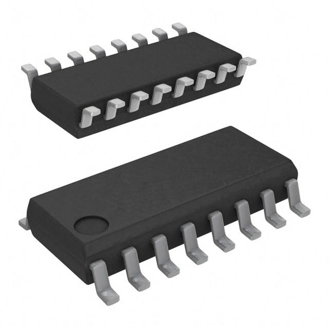
CD74HCT259MG4
Product Overview
- Category: Integrated Circuit (IC)
- Use: Data Storage and Control
- Characteristics: High-Speed, CMOS Logic, 8-Bit Addressable Latch
- Package: SOIC (Small Outline Integrated Circuit)
- Essence: A versatile latch used for data storage and control in various electronic systems.
- Packaging/Quantity: Available in reels or tubes, typically sold in quantities of 250 or 1000 units.
Specifications
- Supply Voltage Range: 2V to 6V
- High-Level Input Voltage: 3.15V (minimum)
- Low-Level Input Voltage: 1.35V (maximum)
- High-Level Output Current: -4mA (maximum)
- Low-Level Output Current: 4mA (maximum)
- Operating Temperature Range: -40°C to +85°C
Detailed Pin Configuration
The CD74HCT259MG4 has a total of 16 pins, each serving a specific function:
- GND: Ground
- QA: Output Q for Bit A
- QB: Output Q for Bit B
- QC: Output Q for Bit C
- QD: Output Q for Bit D
- QE: Output Q for Bit E
- QF: Output Q for Bit F
- QG: Output Q for Bit G
- QH: Output Q for Bit H
- MR: Master Reset
- SH/LD: Shift/Load Control
- CLK: Clock Input
- A0: Address Input A0
- A1: Address Input A1
- A2: Address Input A2
- VCC: Positive Power Supply
Functional Features
- 8-Bit Addressable Latch: Allows individual control over each bit for data storage and retrieval.
- Shift/Load Control: Enables shifting of data or loading new data into the latch.
- Master Reset: Resets all outputs to a low logic level when activated.
- High-Speed Operation: Suitable for applications requiring fast data processing.
Advantages and Disadvantages
Advantages: - Versatile and widely used in various electronic systems. - High-speed operation allows for efficient data handling. - Individual control over each bit provides flexibility in data storage and retrieval.
Disadvantages: - Limited output current capacity may restrict usage in certain applications. - Requires external clock signal for proper operation.
Working Principles
The CD74HCT259MG4 is an 8-bit addressable latch that can store and control data. It operates based on the clock input (CLK) and the shift/load control (SH/LD) signal. When the SH/LD signal is high, the data at the A0-A2 inputs is loaded into the latch. On the falling edge of the CLK signal, the data is transferred from the input to the corresponding output pins. The latch can be reset using the master reset (MR) input, which sets all outputs to a low logic level.
Detailed Application Field Plans
The CD74HCT259MG4 finds applications in various fields, including:
- Data Storage Systems: Used for addressable data storage in memory devices.
- Control Systems: Employed for controlling multiple devices or components based on stored data.
- Communication Systems: Utilized for data routing and switching purposes.
- Display Systems: Integrated into display drivers for controlling individual segments or pixels.
- Industrial Automation: Incorporated in control circuits for process automation and monitoring.
Detailed and Complete Alternative Models
- SN74HC259N: Similar 8-bit addressable latch with comparable specifications.
- CD4014BE: 8-bit static shift register with parallel load capability.
- 74HC595: 8-bit serial-in, serial or parallel-out shift register with output latches.
These alternative models offer similar functionality and can be considered as substitutes for the CD74HCT259MG4 in various applications.
Word count: 487 words
قم بإدراج 10 أسئلة وإجابات شائعة تتعلق بتطبيق CD74HCT259MG4 في الحلول التقنية
Sure! Here are 10 common questions and answers related to the application of CD74HCT259MG4 in technical solutions:
Q: What is CD74HCT259MG4? A: CD74HCT259MG4 is a high-speed CMOS logic device, specifically a 8-bit addressable latch with 3-state outputs.
Q: What are the key features of CD74HCT259MG4? A: Some key features include high-speed operation, wide operating voltage range, 3-state outputs, and compatibility with TTL inputs.
Q: How can CD74HCT259MG4 be used in technical solutions? A: It can be used for various applications such as address decoding, data storage, multiplexing, and bus interfacing.
Q: What is the maximum operating frequency of CD74HCT259MG4? A: The maximum operating frequency is typically around 50 MHz.
Q: What is the power supply voltage range for CD74HCT259MG4? A: The power supply voltage range is typically between 4.5V and 5.5V.
Q: Can CD74HCT259MG4 be used with both CMOS and TTL inputs? A: Yes, CD74HCT259MG4 is compatible with both CMOS and TTL input levels.
Q: Does CD74HCT259MG4 have any protection features? A: Yes, it has built-in diode clamps on all inputs to protect against electrostatic discharge (ESD).
Q: What is the output current capability of CD74HCT259MG4? A: The output current capability is typically around 4 mA.
Q: Can CD74HCT259MG4 be cascaded to increase the number of addressable latches? A: Yes, multiple CD74HCT259MG4 devices can be cascaded together to increase the number of addressable latches.
Q: Are there any specific precautions to consider when using CD74HCT259MG4? A: It is important to follow the recommended operating conditions, avoid exceeding the maximum ratings, and properly handle ESD-sensitive devices during assembly and usage.
Please note that the answers provided here are general and may vary depending on the specific datasheet and manufacturer's recommendations for CD74HCT259MG4.


