

CDCVF2509PW
Overview
Category: Integrated Circuit
Use: Clock Driver
Characteristics: High-speed, low-skew, low-jitter
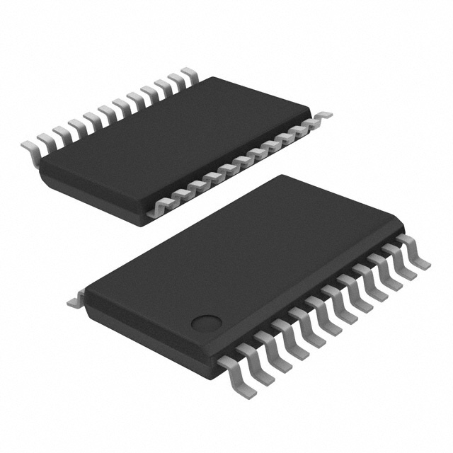
Package: TSSOP-16
Essence: Clock distribution and buffering
Packaging/Quantity: Tape & Reel, 2500 units per reel
Specifications and Parameters
- Supply Voltage: 2.3V to 3.6V
- Input Frequency Range: 1MHz to 200MHz
- Output Frequency Range: 1MHz to 200MHz
- Number of Outputs: 9
- Output Skew: 50ps (maximum)
- Output Jitter: 100fs (typical)
Pin Configuration
The CDCVF2509PW has a total of 16 pins. The pin configuration is as follows:
- VDD
- GND
- OUT0
- OUT1
- OUT2
- OUT3
- OUT4
- OUT5
- OUT6
- OUT7
- OUT8
- OE#
- CLK
- SEL0
- SEL1
- SEL2
Functional Characteristics
- Provides clock distribution and buffering for up to 9 outputs
- Low output skew ensures synchronized clock signals
- Low output jitter ensures accurate timing
- Selectable output frequency range for flexibility
- Output enable control for power management
Advantages and Disadvantages
Advantages: - High-speed operation - Low skew and jitter - Flexible output frequency range - Power management features
Disadvantages: - Limited number of outputs (9)
Applicable Range of Products
The CDCVF2509PW is suitable for various applications that require clock distribution and buffering, such as: - Microprocessors - Digital signal processors - Networking equipment - Communication systems
Working Principles
The CDCVF2509PW receives an input clock signal and distributes it to the 9 output pins. The device buffers and amplifies the input signal to ensure proper voltage levels and drive capability for each output. The selectable output frequency range allows for customization based on specific application requirements.
Detailed Application Field Plans
- Microprocessor Clock Distribution: The CDCVF2509PW can be used to distribute a high-frequency clock signal to multiple microprocessors in a system, ensuring synchronized operation.
- Digital Signal Processing: In DSP applications, the CDCVF2509PW can provide synchronized clock signals to multiple DSP chips, enabling precise timing for data processing.
- Networking Equipment: The device can be utilized in networking equipment, such as routers and switches, to distribute clock signals for synchronization between different components.
- Communication Systems: The CDCVF2509PW is suitable for communication systems that require accurate timing, such as base stations and wireless transceivers.
Detailed Alternative Models
- CDCVF2509PWR: Similar to CDCVF2509PW, but available in a smaller package (SOIC-16).
- CDCVF2509EVM: Evaluation module for testing and prototyping with the CDCVF2509PW.
- CDCVF2509RGZT: RoHS-compliant version of the CDCVF2509PW, suitable for environmentally conscious applications.
5 Common Technical Questions and Answers
Q: What is the maximum operating frequency of the CDCVF2509PW? A: The CDCVF2509PW can operate up to 200MHz.
Q: Can I use the CDCVF2509PW with a supply voltage below 2.3V? A: No, the CDCVF2509PW requires a supply voltage between 2.3V and 3.6V.
Q: How many outputs does the CDCVF2509PW have? A: The CDCVF2509PW has a total of 9 outputs.
Q: What is the typical output jitter of the CDCVF2509PW? A: The typical output jitter is 100fs.
Q: Does the CDCVF2509PW support power management features? A: Yes, the device has an output enable control for power management purposes.
This encyclopedia entry provides an overview of the CDCVF2509PW clock driver integrated circuit. It includes information on its category, use, characteristics, package, specifications, pin configuration, functional characteristics, advantages and disadvantages, applicable range of products, working principles, detailed application field plans, alternative models, and common technical questions and answers.