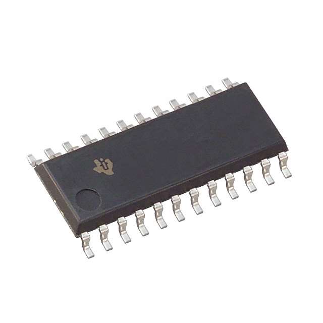
SN74ABT651NSRE4
Product Overview
- Category: Integrated Circuit
- Use: Bus Transceiver
- Characteristics: High-speed, low-power, bidirectional communication
- Package: 56-pin SSOP (Shrink Small Outline Package)
- Essence: Transfers data between two buses with different voltage levels
- Packaging/Quantity: Tape and reel, 2500 units per reel
Specifications
- Supply Voltage Range: 2 V to 5.5 V
- Operating Temperature Range: -40°C to +85°C
- Input/Output Compatibility: TTL, CMOS
- Maximum Data Rate: 100 Mbps
- Number of Channels: 8
- Output Drive Capability: ±12 mA
Pin Configuration
The SN74ABT651NSRE4 has a total of 56 pins. The pin configuration is as follows:
- OE1 (Output Enable 1)
- A1 (Data Bus A1)
- B1 (Data Bus B1)
- GND (Ground)
- B2 (Data Bus B2)
- A2 (Data Bus A2)
- OE2 (Output Enable 2)
- DIR (Direction Control)
- A3 (Data Bus A3)
- B3 (Data Bus B3)
- VCC (Supply Voltage)
- B4 (Data Bus B4)
- A4 (Data Bus A4)
- OE3 (Output Enable 3)
- A5 (Data Bus A5)
- B5 (Data Bus B5)
- GND (Ground)
- B6 (Data Bus B6)
- A6 (Data Bus A6)
- OE4 (Output Enable 4)
- DIR (Direction Control)
- A7 (Data Bus A7)
- B7 (Data Bus B7)
- VCC (Supply Voltage)
- B8 (Data Bus B8)
- A8 (Data Bus A8)
- OE5 (Output Enable 5)
- A9 (Data Bus A9)
- B9 (Data Bus B9)
- GND (Ground)
- B10 (Data Bus B10)
- A10 (Data Bus A10)
- OE6 (Output Enable 6)
- DIR (Direction Control)
- A11 (Data Bus A11)
- B11 (Data Bus B11)
- VCC (Supply Voltage)
- B12 (Data Bus B12)
- A12 (Data Bus A12)
- OE7 (Output Enable 7)
- A13 (Data Bus A13)
- B13 (Data Bus B13)
- GND (Ground)
- B14 (Data Bus B14)
- A14 (Data Bus A14)
- OE8 (Output Enable 8)
- DIR (Direction Control)
- A15 (Data Bus A15)
- B15 (Data Bus B15)
- VCC (Supply Voltage)
- B16 (Data Bus B16)
- A16 (Data Bus A16)
- OE9 (Output Enable 9)
- A17 (Data Bus A17)
- B17 (Data Bus B17)
- GND (Ground)
Functional Features
- Bidirectional data transfer between two buses
- High-speed operation with low power consumption
- TTL and CMOS compatible inputs and outputs
- Output enable control for each channel
- Direction control for selecting the direction of data flow
Advantages and Disadvantages
Advantages: - High-speed data transfer - Low power consumption - Compatibility with TTL and CMOS logic levels - Individual control for each channel
Disadvantages: - Limited number of channels (8 in this case) - Requires careful handling due to small package size
Working Principles
The SN74ABT651NSRE4 is a bus transceiver that enables bidirectional communication between two buses with different voltage levels. It operates by controlling the direction of data flow using the DIR pin. When DIR is set to high, data is transferred from Bus A to Bus B, and when DIR is set to low, data is transferred from Bus B to Bus A. The output enable pins (OE1-OE9) allow individual control over each channel's output.
Detailed Application Field Plans
The SN74ABT651NSRE4 is commonly used in various applications, including:
- Data communication systems
- Networking equipment
- Industrial automation
- Automotive electronics
- Medical devices
- Test and measurement instruments
Alternative Models
Here are some alternative models that can be considered as alternatives to the SN74ABT651
قم بإدراج 10 أسئلة وإجابات شائعة تتعلق بتطبيق SN74ABT651NSRE4 في الحلول التقنية
Sure! Here are 10 common questions and answers related to the application of SN74ABT651NSRE4 in technical solutions:
Q: What is the SN74ABT651NSRE4? A: The SN74ABT651NSRE4 is a 16-bit bus transceiver with 3-state outputs, designed for asynchronous communication between data buses.
Q: What is the voltage range supported by SN74ABT651NSRE4? A: The SN74ABT651NSRE4 supports a voltage range of 4.5V to 5.5V.
Q: Can I use SN74ABT651NSRE4 for bidirectional communication? A: Yes, the SN74ABT651NSRE4 is designed for bidirectional communication between two data buses.
Q: How many data lines can be controlled by SN74ABT651NSRE4? A: The SN74ABT651NSRE4 can control up to 16 data lines.
Q: What is the maximum data transfer rate supported by SN74ABT651NSRE4? A: The SN74ABT651NSRE4 supports a maximum data transfer rate of 200 MHz.
Q: Does SN74ABT651NSRE4 have built-in ESD protection? A: Yes, the SN74ABT651NSRE4 has built-in ESD protection to prevent damage from electrostatic discharge.
Q: Can I use SN74ABT651NSRE4 in industrial applications? A: Yes, the SN74ABT651NSRE4 is suitable for use in industrial applications due to its robust design and wide operating temperature range.
Q: What is the power supply voltage required for SN74ABT651NSRE4? A: The SN74ABT651NSRE4 requires a power supply voltage of 5V.
Q: Does SN74ABT651NSRE4 support hot-swapping of data buses? A: No, the SN74ABT651NSRE4 does not support hot-swapping. It is recommended to disable the outputs before swapping data buses.
Q: Can I use SN74ABT651NSRE4 in low-power applications? A: No, the SN74ABT651NSRE4 is not specifically designed for low-power applications. It has higher power consumption compared to some other ICs optimized for low-power operation.
Please note that these answers are general and may vary depending on the specific requirements and application of the SN74ABT651NSRE4 in your technical solution.


