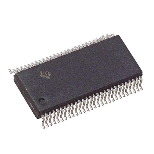
SN74CBT16211CDLR
Product Overview
- Category: Integrated Circuit (IC)
- Use: Digital Multiplexer/Demultiplexer
- Characteristics: High-speed, low-power consumption
- Package: 56-pin VQFN package
- Essence: A multiplexer/demultiplexer IC designed for digital signal routing
- Packaging/Quantity: Tape and reel packaging, 2500 units per reel
Specifications
- Number of Channels: 24
- Input Voltage Range: 0V to VCC
- Output Voltage Range: 0V to VCC
- Supply Voltage Range: 2V to 3.6V
- Operating Temperature Range: -40°C to +85°C
- Input Capacitance: 4pF
- On-state Resistance: 5Ω (typical)
Detailed Pin Configuration
The SN74CBT16211CDLR has a total of 56 pins. The pin configuration is as follows:
- OE (Output Enable) 1
- I/O0 (Input/Output) 0
- I/O1
- GND (Ground)
- I/O2
- I/O3
- VCC (Supply Voltage)
- I/O4
- I/O5
- I/O6
- I/O7
- I/O8
- I/O9
- I/O10
- I/O11
- I/O12
- I/O13
- I/O14
- I/O15
- I/O16
- I/O17
- I/O18
- I/O19
- I/O20
- I/O21
- I/O22
- I/O23
- GND
- I/O24
- I/O25
- I/O26
- I/O27
- I/O28
- I/O29
- I/O30
- I/O31
- I/O32
- I/O33
- I/O34
- I/O35
- I/O36
- I/O37
- I/O38
- I/O39
- I/O40
- I/O41
- I/O42
- I/O43
- I/O44
- I/O45
- I/O46
- I/O47
- GND
- OE (Output Enable) 2
- I/O48
- VCC
Functional Features
- High-speed switching capability
- Low power consumption
- Wide input/output voltage range
- Bidirectional signal routing
- Output enable control for individual channels
Advantages and Disadvantages
Advantages: - High-speed operation allows for efficient data transfer - Low power consumption helps in reducing energy usage - Wide input/output voltage range provides flexibility in signal compatibility - Bidirectional signal routing simplifies circuit design - Individual channel output enable control enhances system control
Disadvantages: - Limited number of channels (24) - Requires external control signals for proper operation
Working Principles
The SN74CBT16211CDLR is a digital multiplexer/demultiplexer IC that routes digital signals between multiple input/output channels. It operates based on the principles of multiplexing and demultiplexing.
In the multiplexing mode, the IC selects one of the input channels and routes it to the output channel based on the control signals provided. This allows multiple input signals to be transmitted through a single output channel.
In the demultiplexing mode, the IC receives a single input signal and routes it to one of the output channels based on the control signals. This allows a single input signal to be distributed to multiple output channels.
The IC operates at high speeds, enabling efficient data transfer. It also consumes low power, making it suitable for battery-powered devices. The wide input/output voltage range ensures compatibility with various digital signal levels.
Detailed Application Field Plans
The SN74CBT16211CDLR is commonly used in various applications, including:
- Data communication systems
- Digital audio/video equipment
- Computer peripherals
- Industrial automation
- Test and measurement instruments
In data communication systems, the IC can be used for multiplexing/demultiplexing data signals between different communication interfaces. In digital audio/video equipment, it can route audio/video signals between different input/output ports. In computer peripherals, it can enable switching between different peripheral devices. In industrial automation, it can facilitate signal routing in control systems. In test and measurement instruments, it can be used for signal selection and distribution.
Detailed and Complete Alternative Models
Some alternative
قم بإدراج 10 أسئلة وإجابات شائعة تتعلق بتطبيق SN74CBT16211CDLR في الحلول التقنية
Sure! Here are 10 common questions and answers related to the application of SN74CBT16211CDLR in technical solutions:
Q: What is SN74CBT16211CDLR? A: SN74CBT16211CDLR is a 24-bit bus switch with 5-volt tolerant inputs and outputs, designed for high-speed switching applications.
Q: What is the maximum operating voltage for SN74CBT16211CDLR? A: The maximum operating voltage for SN74CBT16211CDLR is 3.6 volts.
Q: What is the typical propagation delay of SN74CBT16211CDLR? A: The typical propagation delay of SN74CBT16211CDLR is around 4.5 nanoseconds.
Q: Can SN74CBT16211CDLR be used for bidirectional data transfer? A: Yes, SN74CBT16211CDLR supports bidirectional data transfer, making it suitable for applications where data needs to be transmitted in both directions.
Q: What is the maximum current that SN74CBT16211CDLR can handle? A: SN74CBT16211CDLR can handle a maximum current of 32 mA per I/O pin.
Q: Does SN74CBT16211CDLR have built-in ESD protection? A: Yes, SN74CBT16211CDLR has built-in ESD protection, which helps safeguard against electrostatic discharge events.
Q: Can SN74CBT16211CDLR be used in hot-swapping applications? A: Yes, SN74CBT16211CDLR supports hot-swapping, allowing for the insertion or removal of devices without interrupting the system operation.
Q: What is the power supply voltage range for SN74CBT16211CDLR? A: The power supply voltage range for SN74CBT16211CDLR is typically between 2.3 volts and 3.6 volts.
Q: Can SN74CBT16211CDLR be used in high-speed data transmission applications? A: Yes, SN74CBT16211CDLR is designed for high-speed switching applications and can support data rates up to several hundred megahertz.
Q: Is SN74CBT16211CDLR available in different package options? A: Yes, SN74CBT16211CDLR is available in various package options, including SOIC, TSSOP, and VQFN, providing flexibility for different design requirements.
Please note that these answers are general and may vary depending on specific application requirements and datasheet specifications.


