

SN74S74NSR
Product Overview
- Category: Integrated Circuit (IC)
- Use: Flip-Flop
- Characteristics: Dual D-Type Positive-Edge-Triggered Flip-Flop
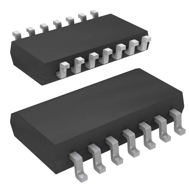
- Package: SOIC (Small Outline Integrated Circuit)
- Essence: The SN74S74NSR is a dual flip-flop IC that can store and transfer data in digital circuits.
- Packaging/Quantity: Available in reels of 2500 units.
Specifications
- Logic Family: TTL (Transistor-Transistor Logic)
- Number of Flip-Flops: 2
- Trigger Type: Positive-Edge
- Clock Frequency: Up to 25 MHz
- Supply Voltage: 4.5V to 5.5V
- Operating Temperature Range: -40°C to +85°C
Detailed Pin Configuration
The SN74S74NSR has a total of 14 pins, which are assigned as follows:
- CLR (Clear) - Active Low Clear Input
- D1 (Data Input 1) - Data Input for Flip-Flop 1
- CLK (Clock) - Clock Input
- D2 (Data Input 2) - Data Input for Flip-Flop 2
- Q1 (Output 1) - Output of Flip-Flop 1
- Q1' (Complementary Output 1) - Complementary Output of Flip-Flop 1
- GND (Ground) - Ground Reference
- Q2' (Complementary Output 2) - Complementary Output of Flip-Flop 2
- Q2 (Output 2) - Output of Flip-Flop 2
- PRE (Preset) - Active Low Preset Input
- PRD (Preset Enable) - Active Low Preset Enable Input
- CLR (Clear Enable) - Active Low Clear Enable Input
- VCC (Supply Voltage) - Positive Power Supply
- PRD (Preset Disable) - Active Low Preset Disable Input
Functional Features
- Dual flip-flop design allows for independent storage and transfer of data in two separate circuits.
- Positive-edge triggering ensures that the flip-flops capture and store data on the rising edge of the clock signal.
- Clear and preset inputs provide control over the initial state of the flip-flops.
- Complementary outputs allow for easy integration with other digital logic circuits.
Advantages and Disadvantages
Advantages
- Dual flip-flop configuration provides flexibility in designing complex digital systems.
- Positive-edge triggering ensures reliable data capture.
- Wide operating temperature range allows for use in various environments.
- TTL logic family offers compatibility with other TTL-based ICs.
Disadvantages
- Limited number of flip-flops per IC may restrict the complexity of certain designs.
- Requires external components for proper operation, such as clock signal source and power supply.
Working Principles
The SN74S74NSR operates based on the principles of positive-edge-triggered flip-flops. When a rising edge is detected on the clock input, the data present at the D1 and D2 inputs are captured and stored in the respective flip-flops. The stored data can then be accessed through the Q1, Q1', Q2, and Q2' outputs. The clear and preset inputs allow for controlling the initial state of the flip-flops, while the complementary outputs facilitate integration with other digital circuits.
Detailed Application Field Plans
The SN74S74NSR is commonly used in various digital applications, including:
- Sequential logic circuits
- Data storage and transfer systems
- Clock synchronization circuits
- Register and counter designs
- Microprocessor-based systems
Detailed and Complete Alternative Models
- SN74LS74N: Dual D-Type Positive-Edge-Triggered Flip-Flop, Low Power Schottky TTL Logic Family.
- CD4013BE: Dual D-Type Flip-Flop, CMOS Logic Family.
- MC74HC74AN: Dual D-Type Flip-Flop, High-Speed CMOS Logic Family.
These alternative models offer similar functionality to the SN74S74NSR and can be used as replacements depending on specific design requirements.
In conclusion, the SN74S74NSR is a dual flip-flop IC belonging to the TTL logic family. It provides reliable data storage and transfer capabilities in digital circuits. With its positive-edge triggering, clear and preset inputs, and complementary outputs, it offers flexibility and compatibility for various applications. However, designers should consider the limited number of flip-flops per IC and the need for external components. Alternative models such as the SN74LS74N, CD4013BE, and MC74HC74AN can be considered based on specific design needs.
قم بإدراج 10 أسئلة وإجابات شائعة تتعلق بتطبيق SN74S74NSR في الحلول التقنية
Sure! Here are 10 common questions and answers related to the application of SN74S74NSR in technical solutions:
Question: What is the SN74S74NSR?
Answer: The SN74S74NSR is a dual D-type positive-edge-triggered flip-flop integrated circuit (IC) manufactured by Texas Instruments.Question: What is the purpose of the SN74S74NSR?
Answer: The SN74S74NSR is used for storing and transferring binary data in digital circuits.Question: What is the operating voltage range of the SN74S74NSR?
Answer: The SN74S74NSR operates within a voltage range of 4.5V to 5.5V.Question: How many flip-flops are there in the SN74S74NSR?
Answer: The SN74S74NSR contains two independent flip-flops, each with separate inputs and outputs.Question: What is the maximum clock frequency supported by the SN74S74NSR?
Answer: The SN74S74NSR can operate at a maximum clock frequency of 55 MHz.Question: Can the SN74S74NSR be used in both synchronous and asynchronous applications?
Answer: Yes, the SN74S74NSR can be used in both synchronous and asynchronous applications depending on the design requirements.Question: What is the setup time requirement for the inputs of the SN74S74NSR?
Answer: The setup time requirement for the inputs of the SN74S74NSR is typically 20 ns.Question: Does the SN74S74NSR have any built-in logic gates?
Answer: No, the SN74S74NSR does not have any built-in logic gates. It is a flip-flop IC that requires external logic circuitry.Question: What is the power consumption of the SN74S74NSR?
Answer: The power consumption of the SN74S74NSR is typically around 10 mW.Question: Can the SN74S74NSR be used in high-speed data transfer applications?
Answer: Yes, the SN74S74NSR can be used in high-speed data transfer applications due to its fast operation and low propagation delay.
Please note that these answers are general and may vary depending on specific application requirements and datasheet specifications.